2.5.3 Guide Value
The guide value is used in all synchronous modes of
operation (CAM mode and Gear mode). It is used as the
master position within the synchronous modes. The guide
value consists of a position value (see
chapter 7.8.1 Parameter: Position Guide Value (0x2060)) and
an optional velocity value (see chapter 7.8.2 Parameter:
Velocity Guide Value (0x2064)).
The servo drive also supports a scaling of the guide value.
The scaling factor (see chapter 7.8.4 Parameter: Guide Value
Scaling Factor (0x3808)) consists of a numerator and a
denominator.
The Position guide value is multiplied by the quotient of
numerator and denominator.
Guide value scaled = Guide value x Scaling factor + Guide value oset
(Internally used = 0x2060 x 0x3808.01/02 + 0x3806)
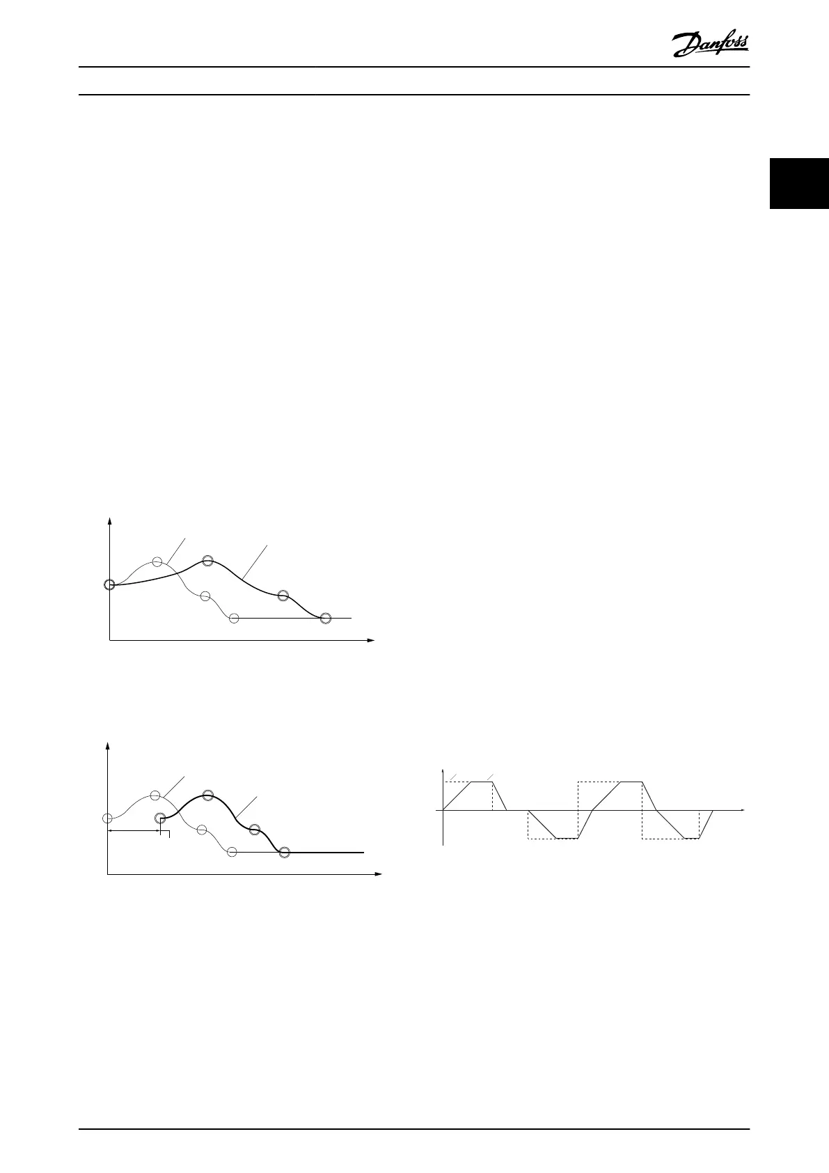
Rotor angle of axis
Master axis / guide value
Original CAM
prole
Used CAM prole
(Original guide value
multiplied with master
scaling factor)
Illustration 2.130 Example of Guide Value Scaling in CAM
Mode
Rotor angle of axis
Master axis / guide value
Original CAM
prole
Used CAM prole
(Original + master oset)
CAM master oset =
Guide value oset
130BF214.10
Illustration 2.131 Example of Position Guide Value Oset in
CAM Mode
When receiving a guide value, the servo drive can
optionally check the value against reversing and jumps in
the position using object 0x2061 (see
chapter 7.8.3 Parameter: Guide Value Option Code (0x2061)).
Using this object, the servo drive can also be instructed to
calculate the guide value velocity.
The guide value objects can be found inchapter 7.8 Guide
Value Objects.
2.5.3.1 Guide Value Reference
The servo drive is also able to provide a guide value that
can be used, for example, by the PLC. This generated guide
value is called Guide value reference. It consists of the
position and the velocity. The servo drive can provide
these values based on dierent sources.
Possible guide value reference sources are:
•
External encoder
•
Simulation
•
Actual target position
- Actual position
- Set position
Select 1 of these using object 0x2063 (see
chapter 7.9.3 Parameter: Guide Value Reference Option Code
(0x2063)). The objects to inuence the guide value
reference can be found in chapter 7.9 Guide Value Reference
Objects.
2.5.3.2 Guide Value Reference Simulation
A guide value reference simulation functionality is
provided (activate/deactivate guide value reference
simulation) by the servo drive. Velocity, acceleration, and
speed limits can be parameterized.
The guide value reference simulation can also be used as a
virtual axis in a real application. The guide value reference
simulation can be useful in commissioning scenarios when
it is not possible/appropriate to use the entire machine.
The guide value reference simulation can then be used to
simulate that the main axis is moving.
Target velocity
Velocity
acc
0
dec
acc dec acc dec
acc dec
Illustration 2.132 Usage of Acceleration and Deceleration in
GuideValue Reference Simulation
The device puts the calculated position and the velocity
into the reference objects (see chapter 7.9.1 Parameter:
Position Guide Value Reference (0x2062) and
chapter 7.9.2 Parameter: Velocity Guide Value Reference
(0x2065)) every cycle while increasing or decreasing the
simulation speed with the desired ramp acceleration until
the demanded speed has been reached.
The guide value reference simulation can be parameterized
with the objects given in chapter 7.9.6 Guide Value
Reference Simulation.
Servo Drive Operation Programming Guide
MG36D102 Danfoss A/S © 01/2017 All rights reserved. 85
2 2

 Loading...


