2.5.2.3 Timing Example
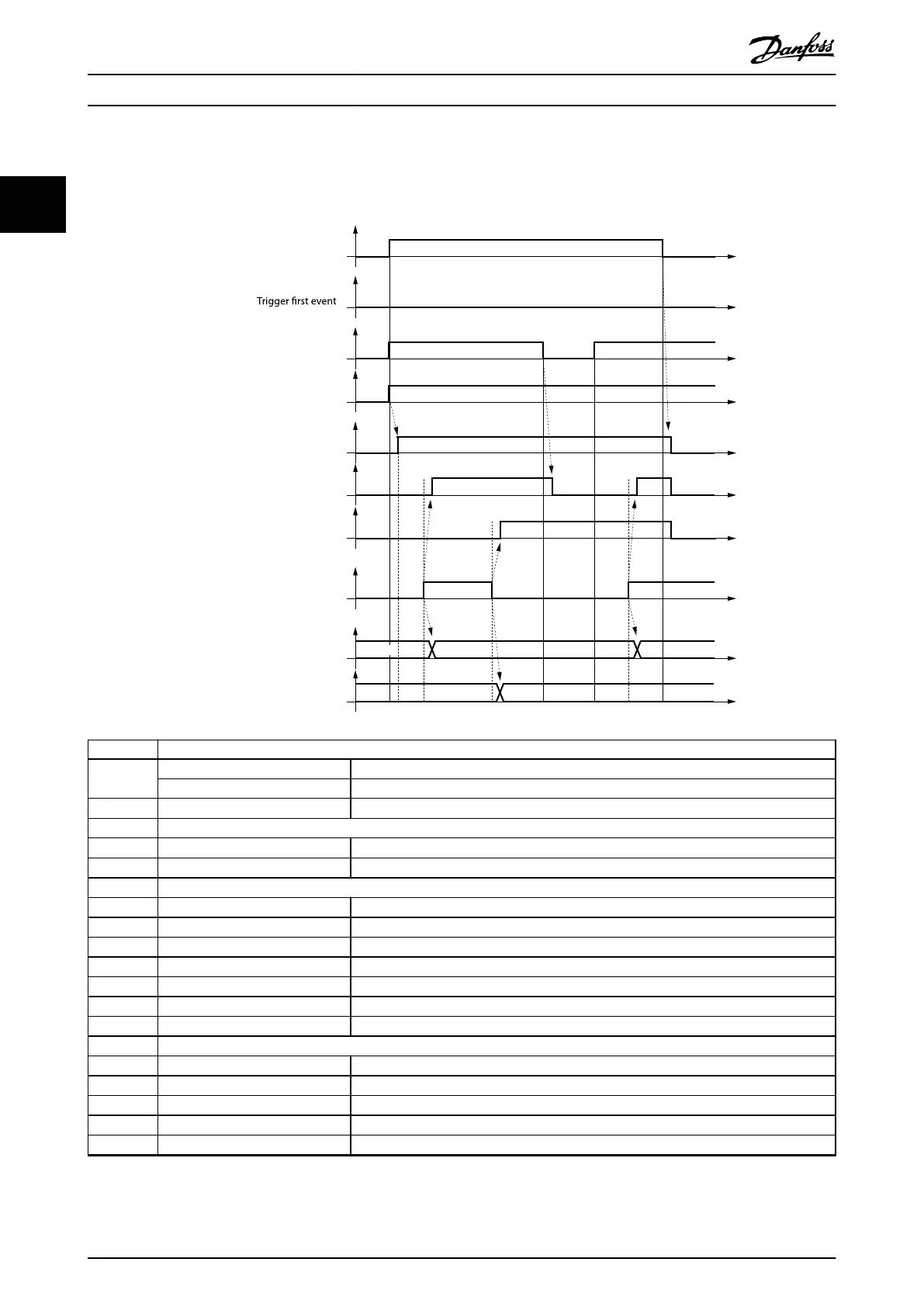
Illustration 2.129 shows a timing diagram for an example touch probe conguration and the corresponding behavior.
0x60B8 bit 0
Enable touch probe 1
0x60B9 bit 0
Touch probe 1 is enabled
0x60B9 bit 1
Touch probe 1 positive edge stored
0x60BA
Touch probe position 1 positive value
0x60BB
Touch probe position 1 negative value
0x60B9 bit 2
Touch probe 1 negative edge stored
Touch probe signal
0x60B8 bit 1
0x60B8 bit 4
Enable sampling at positive edge
0x60B8 bit 5
Enable sampling at negative edge
1
1
13
2
7 9
84
12
14
14
146
3 5 11
4a 8a 10 12a
14a6a
0000 yyyy
xxxx0000
uuuu
Number Touch probe behavior
1 0x60B8, bit 0 = 1
b
Enable touch probe 1.
0x60B8, bit 1, 4, 5 Congure and enable touch probe 1 positive and negative edge.
2
→ 0x60B9 bit 0 = 1
b
Status Touch probe 1 enabled is set.
3 External touch probe signal has positive edge
4
→ 0x60B9 bit 1 = 1
b
Status Touch probe 1 positive edge stored is set.
4a
→ 0x60BA
Touch probe position 1 positive value is stored.
5 External touch probe has negative edge
6
→ 0x60B9 bit 2 = 1
b
Status Touch probe 1 negative edge stored is set
6a
→ 0x60BB
Touch probe position 1 negative value is stored.
7 0x60B8, bit 4 = 0
b
Sample positive edge is disabled.
8
→ 0x60B9 bit 0 = 0
b
Status Touch probe 1 positive edge stored is reset.
8a
→ 0x60BA
Touch probe position 1 positive value is not changed
9 0x60B8, bit 4 = 1
b
Sample positive edge is enabled.
10
→ 0x60BA
Touch probe position 1 positive value is not changed.
11 External touch probe signal has positive edge.
12
→ 0x60B9 bit 1=1
b
Status Touch probe 1 positive edge stored is set.
12a
→ 0x60BA
Touch probe position 1 positive value is stored.
13 0x60B8, bit 0 = 0
b
Touch probe 1 is disabled.
14
→ 0x60B9 bit 0, 1, 2 = 0
b
Status bits are reset.
14a
→ 0x60BA, 0x60BB
Touch probe position 1 positive/negative values are not changed.
Illustration 2.129 Timing Diagram for Touch Probe Example
Servo Drive Operation
VLT
®
Integrated Servo Drive ISD
®
510 System
84 Danfoss A/S © 01/2017 All rights reserved. MG36D102
22

 Loading...


