The status of the touch probe can be obtained using
object 0x60B9 (see chapter 7.18.2 Parameter: Touch Probe
Status (0x60B9)). The position results are given in objects
0x60BA–0x60BD (see chapter 7.18.3 Parameter 51-51: Touch
Probe 1 Positive Edge (0x60BA) to chapter 7.18.6 Parameter
51-64: Touch Probe 2 Negative Edge (0x60BD)). The
corresponding time stamps can be read using the objects
0x60D1–0x60D4 (see chapter 7.18.10 Parameter 51-53: Touch
Probe Time Stamp 1 Positive Value (0x60D1) to
chapter 7.18.13 Parameter 51-66: Touch Probe Time Stamp 2
Negative Value (0x60D4)).
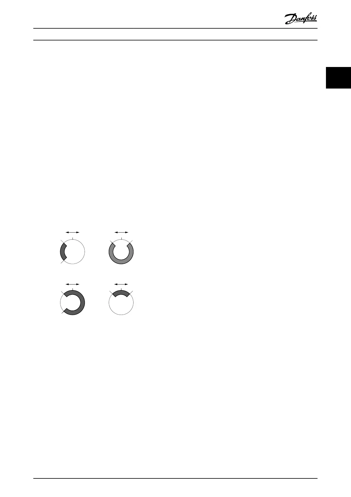
2.5.2.1 Touch Probe Window
For touch probe events it is possible to dene a window. If
this functionality is activated (for touch probe 1: object
0x60B8 bit 6 = 1, and for touch probe 2: object 0x60B8 bit
14 = 1), touch probe events are only accepted within this
window. The window is congured using objects 0x3853:
First position (see chapter 7.18.8 Parameter: First Position
(0x3853)) and 0x3854: Last position (see
chapter 7.18.9 Parameter: Last Position (0x3854)).
A. FirstPosition < LastPosition
B. FirstPosition > LastPosition
LastPosition LastPosition
FirstPosition
FirstPosition
LastPosition
LastPositionFirstPosition
FirstPosition
0 0
0
0
accepted
accepted
accepted
accepted
accepted
– + – +
– + – +
130BF239.10
Illustration 2.128 Examples of Windows where Trigger Events
are Accepted (For Modulo Axes)
2.5.2.2 Touch Probe Edge Counter for
Continuous Mode
Touch probe edge counter for continuous mode
For continuous touch probe mode (0x60B8 bit 1 = 1, or
0x60B8 bit 9 = 1), a counter per touch probe channel is
incremented on each touch probe event. Therefore, the
control device may check how many touch probe events
occur between the control cycles. A counter object is
dened per touch probe and per edge. See objects:
•
0x60D5 (chapter 7.18.14 Parameter 51-52: Touch
Probe 1 Positive Edge Counter (0x60D5))
•
0x60D6 (chapter 7.18.15 Parameter 51-55: Touch
Probe 1 Negative Edge Counter (0x60D6))
•
0x60D7 (chapter 7.18.16 Parameter 51-62: Touch
Probe 2 Positive Edge Counter (0x60D7))
•
0x60D8 (chapter 7.18.17 Parameter 51-65: Touch
Probe 2 Negative Edge Counter (0x60D8))
Servo Drive Operation Programming Guide
MG36D102 Danfoss A/S © 01/2017 All rights reserved. 83
2 2

 Loading...


