1000 10002000 3000 4000 5000
Switch03
Switch03
Switch01
Position
Axis is moving continuously in positive direction
130BF575.10
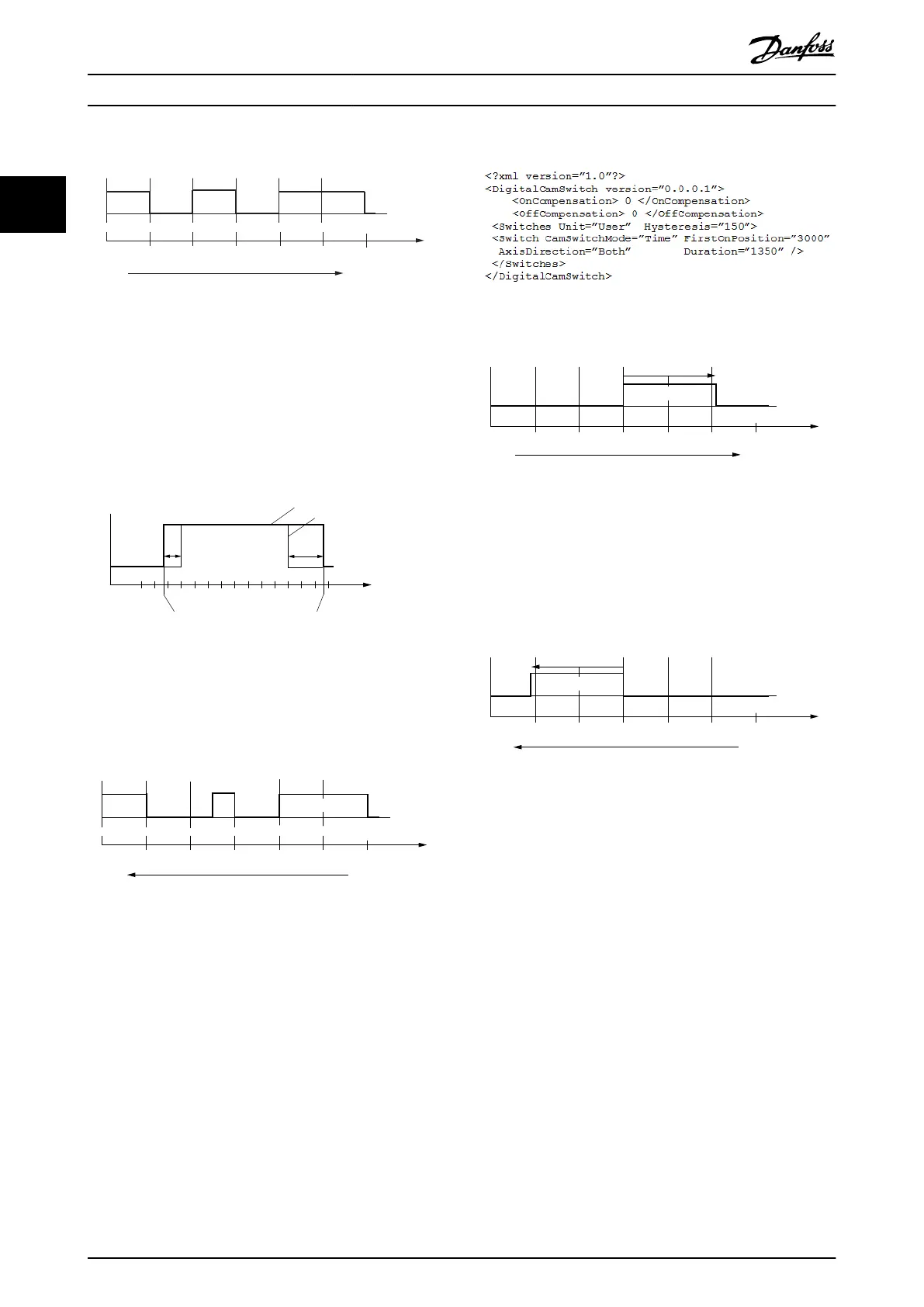
Illustration 2.122 Example 1 - Behavior of Output in Positive
Direction
Illustration 2.122 shows the behavior of the output when
the axis is moving continuously in a positive direction. The
axis is a modulo axis with a modulo length of 5000. It does
not include on/o compensation or hysteresis.
125
ms
250
ms
Switch01
Resulting output with delay
Without delay
2000 2500
3000
Resulting position depends on the current velocity
130BF235.10
Illustration 2.123 Example 1 - Use of On/O Compensation
Illustration 2.123 shows the additional use of on compen-
sation of 125 ms and o compensation of 250 ms. The axis
is moving continuously in a positive direction.
Switch03
Switch02
Switch03
Axis is moving continously in negative direction
Position1000 3000 5000 100040002000
Illustration 2.124 Example 1 - Behavior of Output in Negative
Direction
Illustration 2.124 shows the behavior of the output when
the axis is moving continuously in a negative direction.
The axis is a modulo axis with a modulo length of 5000. It
does not include on/o compensation or hysteresis.
Example 2:
Illustration 2.125 Example 2
Switch04
Axis is moving continously in positive direction
Position1000 3000 5000 100040002000
Illustration 2.126 Example 2- Behavior of Output in Positive
Direction
Illustration 2.126 shows the behavior of the output when
the axis is moving continuously in a positive direction. The
axis is a modulo axis with a modulo length of 5000. It does
not include on/o compensation or hysteresis.
Switch04
Axis is moving continously in negative direction
Position1000 3000 5000 100040002000
Illustration 2.127 Example 2- Behavior of Output in Negative
Direction
Illustration 2.127 shows the behavior of the output when
the axis is moving continuously in a negative direction.
The axis is a modulo axis with a modulo length of 5000. It
does not include on/o compensation or hysteresis.
2.5.2 ISD Touch Probe
This functionality stores the position actual value and a
time stamp at the rising or falling edge of the congured
digital input. This functionality is available in all modes of
operation for each input individually.
The function is
congured using object 0x60B8 (see
chapter 7.18.1 Parameter: Touch Probe Function (0x60B8)),
where the dierent options regarding the trigger event
can be selected.
Servo Drive Operation
VLT
®
Integrated Servo Drive ISD
®
510 System
82 Danfoss A/S © 01/2017 All rights reserved. MG36D102
22

 Loading...


