Number Description
26 Outputs UDC active
Table 3.2 Relay Control Functions
3.3 Monitoring
The SAB monitors the voltages and currents in the input
and output lines, for example the auxiliary line and the
DC-link, so that a phase loss or other errors can be
detected. These values provide detailed information on the
current load. The information is available via the eldbus,
the LCP, and the ISD Toolbox.
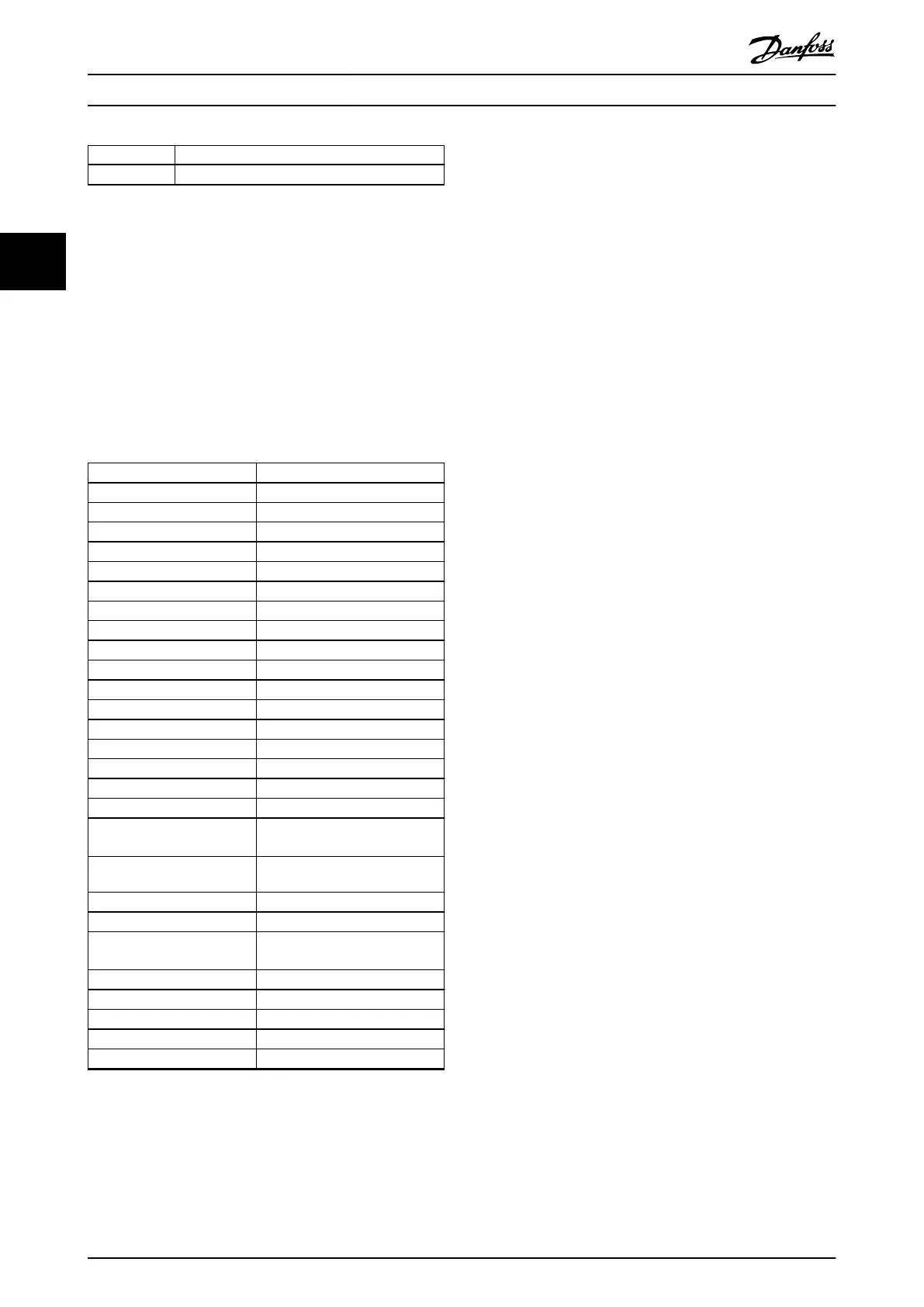
The SAB monitors the signals detailed in Table 3.3 and
provides the measured values via the eldbus and the LCP.
Signal name Description
DC-link voltage DC-link voltage
Warning code Warning code
Error code Error code
Temperature control card Temperature control card
Temperature power card Temperature power card
Temperature SAB card Temperature SAB card
External encoder position External encoder position
External encoder speed External encoder speed
UDC 1 current Current ow on DC-link line 1
UDC 2 current Current ow on DC-link line 2
AUX line 1 current Current on AUX Line 1
AUX line 2 current Current on AUX Line 2
AUX line voltage AUX line voltage
Brake chopper gate Brake chopper gate
Brake chopper feedback Brake chopper feedback
UDC Over-Inrush UDC current over-inrush
UDC Bypass-Inrush UDC Current bypass-inrush
UDC back current Current (link voltage) back from
the servo drives
Inrush relay power card Inrush relay power card
Inrush relay SAB card Inrush relay SAB card
DC leakage current DC leakage current
Brake resistor power
monitoring
Brake resistor power monitoring
DC link total current DC link total current
DC link total current raw DC link total current (unltered)
UDC 1 ow (ltered) UDC 1 current readout
UDC 2 ow (ltered) UDC 2 current readout
Controlword Controlword
Table 3.3 Signals Monitored by the SAB
Use the ISD Toolbox Scope subtool to perform a trace on
these signals. If the overload situation is critical, the SAB
protects itself and the servo drives by shutting down to
prevent any damage. In such cases, warnings may not be
visible if the shutdown occurs quickly.
3.3.1 AUX Output
The SAB protects the servo drives connected to the AUX
lines against overcurrent, overvoltage, and undervoltage. If
an overload occurs, the outputs are disabled and an alarm
is issued. If the UDC outputs are enabled, they are disabled
rst.
For overvoltage and undervoltage conditions, an
associated warning with a dierent threshold is triggered
before the error. Set a user current limit in steps of 0.1
amperes for each of the auxiliary lines in object 0x2003,
sub-indexes 4 and 5 (see chapter 8.5 Object 0x2003: U
AUX
Related Values). If this limit is reached, the SAB disables the
auxiliary lines. If the current reaches 90% of the limit set, a
warning is issued. The SAB has additional hardware
detection/protection in case a hard short circuit occurs on
the auxiliary lines.
3.3.2 DC Output
The SAB protects itself and the servo drives connected to
the UDC lines against overcurrent, overvoltage, and
undervoltage. If an overload occurs, the outputs are
disabled and an alarm is issued.
For overvoltage and undervoltage conditions, an
associated warning with a dierent threshold is triggered
before the error. The SAB provides short-term overload
capabilities; it is possible to run at 160% load for 60 s.
However, afterwards, the SAB must run at a reduced
output load to compensate the overload. The SAB has an
internal monitoring logic for the overload condition and its
duration.
3.3.3 Brake Control and Monitoring
Connect a brake resistor to the SAB to limit the UDC
voltage when the connected servo drives are in
recuperation mode and acting as a generator. If
congured, the SAB limits the UDC voltage by connecting
the resistor via an internal IGBT switch. To monitor the
functionality of the brake, the brake circuitry, and the
brake power dissipation, make the following settings:
•
Enter the correct resistance in object 0x2031 (see
chapter 8.11 Object 0x2031: Brake Resistor).
•
Enter the correct power limit in object 0x2032
(see chapter 8.12 Object 0x2032: Brake Resistor
Power Limit).
If any congured limit is overstepped, the SAB issues a
warning or alarm. If congured to report an alarm, the SAB
transitions to fault state. Reinitialize the SAB using the
error recover command in the SAB state machine.
Servo Access Box (SAB) Oper...
VLT
®
Integrated Servo Drive ISD
®
510 System
92 Danfoss A/S © 01/2017 All rights reserved. MG36D102
33

 Loading...


