32
SECTION 5 - REMOVAL - REFITTING OF THE MAIN ENGINE COMPONENTS
CURSOR SERIES
Base - 03/2015 Print P4D32C006 E
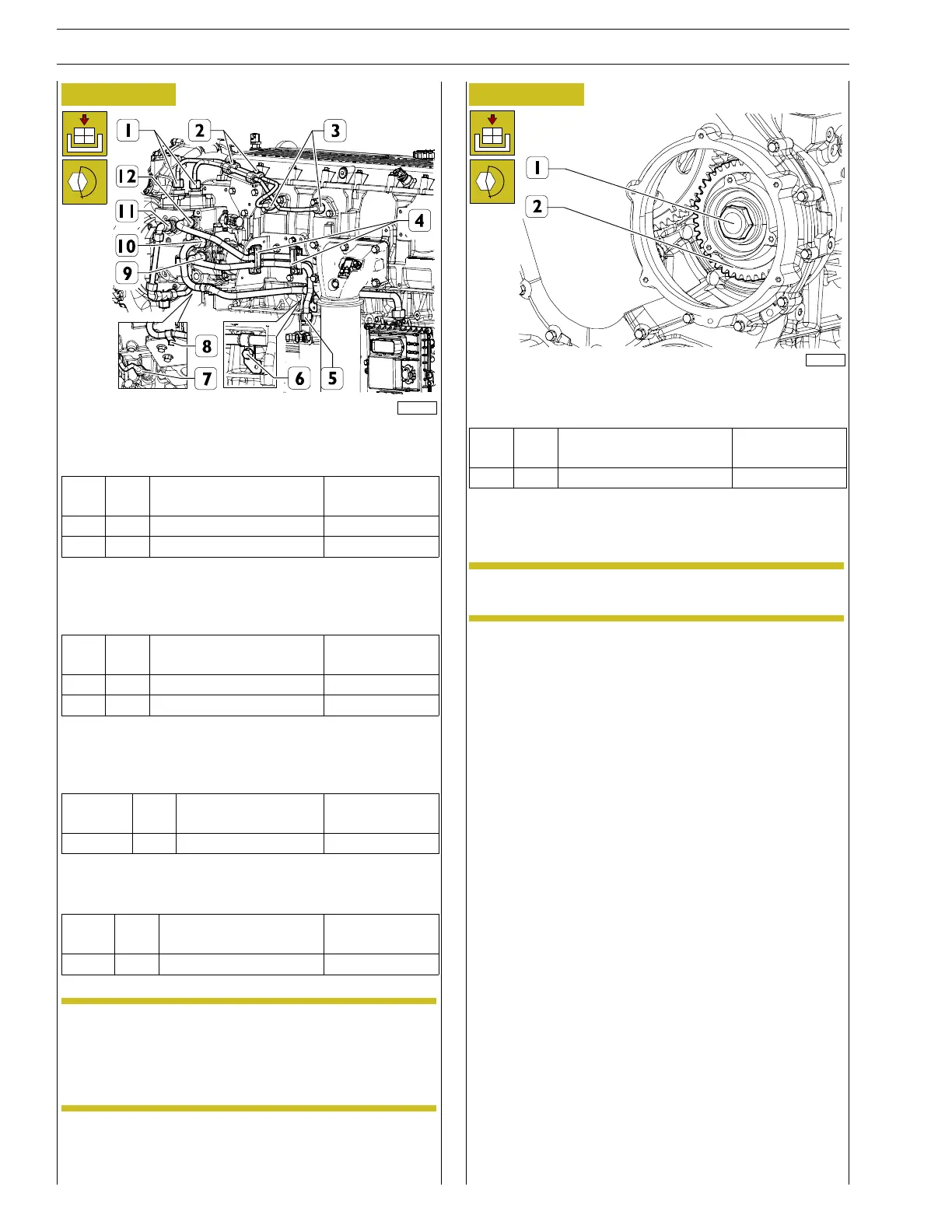
Figure 87
227770
Fit the HP fuel pipes, fit the plugs onto the bracket and tighten
the fittings (1, 3) and nuts to the torque (2) shown in the table.
Ref.
No. Description
Tightening
torques
(1, 3) 4 Fittings M16 X 1.5 42.5±2Nm
(2) 2 Nuts M6 X 1 8±2Nm
Position the LP fuel pipe from control unit to pump, tighten the
fitting (10)and bracket screws (6, 8) to the torque shown in the
table.
Ref.
No. Description
Tightening
torques
(10) 1 Fitting M22 X 1.5 50 ± 5 Nm
(6, 8) 2 Screws M8 X 1.25 X 16 24.5 ± 2.5 Nm
Position the LP fuel pipe from pump to filter and vivc-versa and
tighten fittings (5, 9, 12) to the torque shown in the table. close
springs (4).
Ref.
No. Description
Tightening
torques
(5, 9 12) 4 Fittings M18 X 1.5 37 ± 3 Nm
Fit the new fuel return pipe (7, 11) and tighten the fittings to
thetorqueindicatedinthetable.
Ref.
No. Description
Tightening
torques
(7, 11) 2 Fittings M18 X 1.5 37 ± 3 Nm
NOTE Make sure that the pipe is not damaged after
mounting and that there are no fuel leaks while
engine is running.
The HP pipes that are disassembled cannot be
used again and must be replaced.
Figure 88
225037
Fit the gear (2) and tighten the nut (1) to the torque shown
in the table.
Ref.
No. Description
Tightening
torques
(1) 1 Nut M24 X 1.5 275 ± 25 Nm
Connect the electrical connection from the fuel flow regulator.
Remove the tool 99360351 for engine flywheel locking.
NOTE Carefully clean the seating of the filter and the
cover.