178241
190509
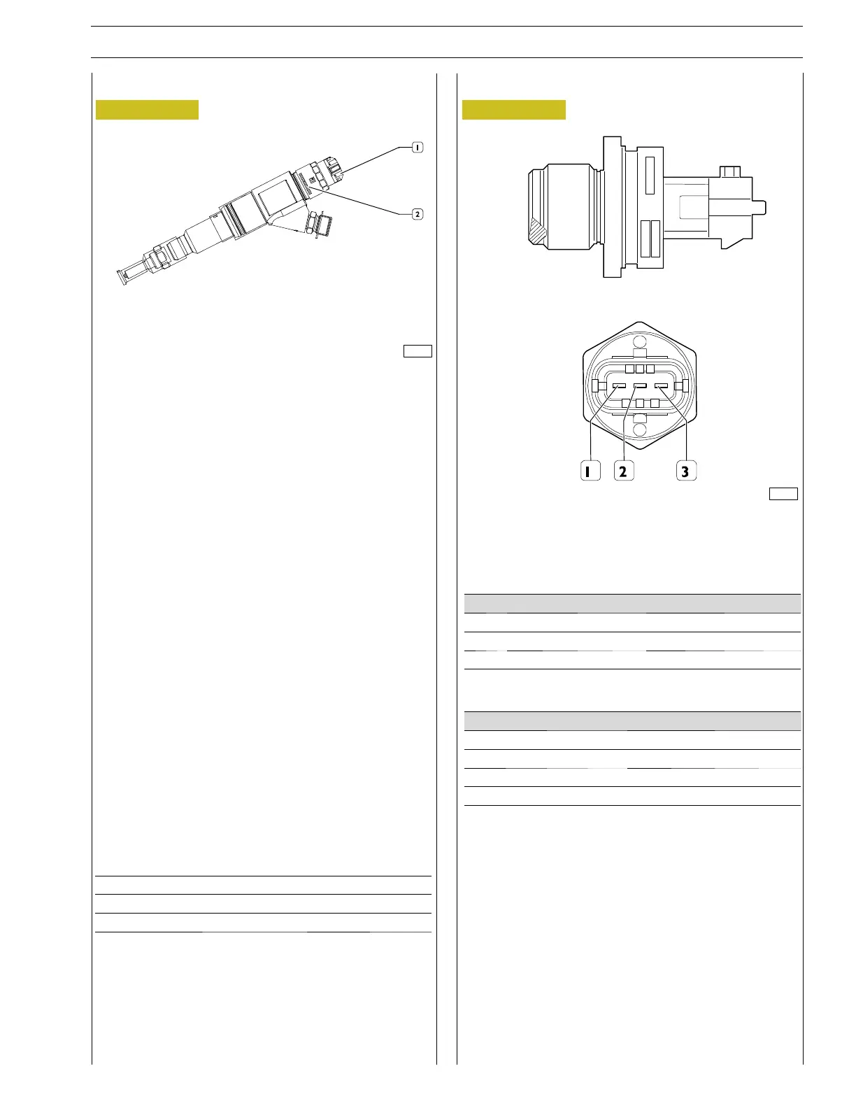
Figure 5 Figure 6
CRIN INJECTOR 3.3
1. Electrical connections - 2. Electromagnet assembly
Rail pressure sensor (RSD 4)
The value of injection pressure is used to keep the pressure
level under control and to determine the time duration of the
injection electronic command.
This is an N.O. solenoid valve.
They are connected to the EDC ECU on connector 2.
The resistance of the coil of each individual injector is 0.56
-0.57.
The electro-injector essentially consists of two parts:
- actuator - spray nozzle consisting of a pressure rod, a
needle and a jet
- control solenoid valve made up of coil and pilot valve
The solenoid valve checks the lift of the nozzle needle.
START OF INJECTION
Upon being supplied with power, the coil moves up the shut-
ter. The fuel in the control volume flows back towards the
return duct resulting in a pressure drop in control volume.
Atthesametime,thefuelpressureinthepressurechamber
moves up the needle resulting into the fuel being injectedinto
the cylinder.
END OF INJECTION
When power to the coil is cut off, the shutter closes again
so as to re-create an equilibrium which moves the needle
back into its closed position and stops the injection process.
SECTION 3 - ELECTRIC EQUIPMENT
9
CURSOR SERIES
Print P4D32C006 E Base - 03/2015
Maximum working pressure 1,800 bar
Minimum working pressure 250 bar
Electrical connection M4 nut 1.5 ±0.25 Nm
Pin Description ECU pin
1 Ground (-) EDC17, pin A/60
2 Signal (Output) EDC17, pin A/36
3 Power supply (+) EDC17, pin A/11
Specifications Measurement Conditions
Pressure range 0 - 2,400 bar
Power supply 5V
Output voltage 0.5 - 4.5V
Closing torque 140 Nm