SECTION 6 - GENERAL MECHANICAL OVERHAUL
55
CURSOR SERIES
Print P4D32C006 E Base - 03/2015
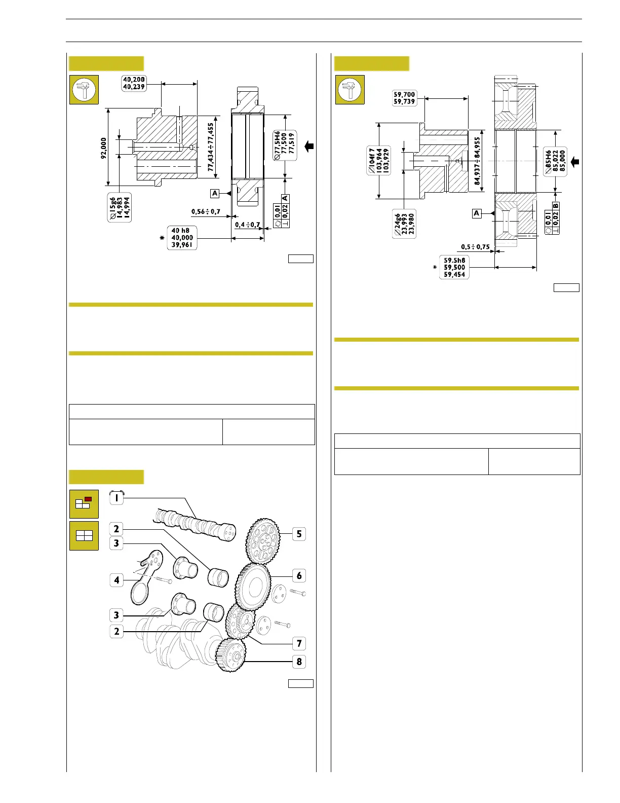
Figure 125
225002
After driving the bushing, bore it to obtain the diameter shown
in the figure.
NOTE The bushing must be driven into the gear in the
direction of the arrow setting the latter to the
dimension shown.
At the end of the boring operation, check that the gear
bushing/journal assembly clearance is equal to the indicated
value.
Technical data
rated assembling clearance
between gear bushings and pins
0.045 - 0.085 mm
Replacement of the dual idle gear bushes
Figure 126
225001
1. Camshaft - 2. Bushing - 3. Pin - 4. Connecting rod -
5. Camshaft l control gear - 6. Transmission gear - 7. Double
transmission gear - 8. Crankshaft driving gear
Replace the bushings (2) when worn.
Figure 127
225003
After driving the bushing, bore it to obtain the diameter shown
in the figure.
NOTE The bushing must be driven into the gear in the
direction of the arrow setting the latter to the
dimension shown.
Check that the nominal assembly clearance between gear
bushings and pins is equal to the value stated below.
Technical data
rated assembling clearance
between gear bushings and pins
0.045 - 0.085 mm
Checking cam lift and camshaft pins alignment