12
SECTION 6 - GENERAL MECHANICAL OVERHAUL
CURSOR SERIES
Base - 03/2015 Print P4D32C006 E
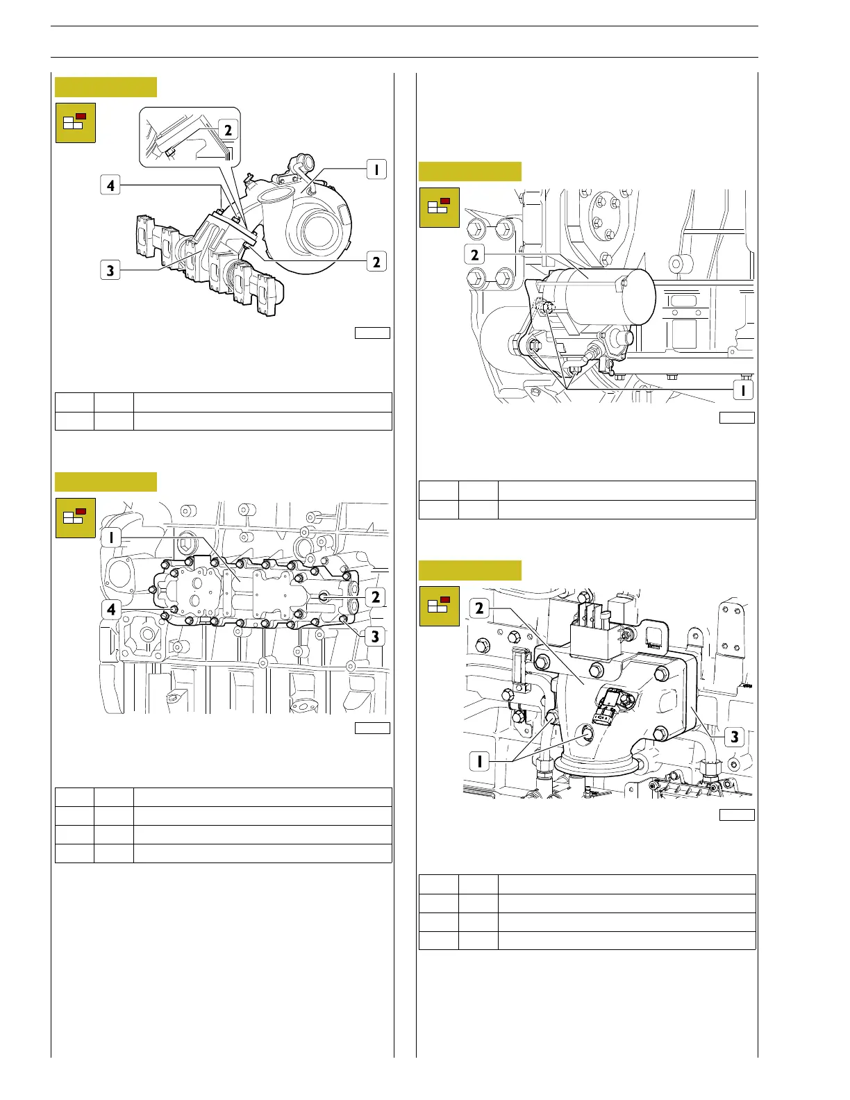
Figure 22
221091
Unscrew the nuts (2, 4) and detach the turbocharger (4) from
the exhaust manifold (3). remove the gasket.
Ref.
No. Description
(2, 4) 4 Nuts M12 X 1.75
Heat exchanger removal
Figure 23
225015
Unscrew the screws (2,3,4) and remove the complete heat ex-
changer (1) and its gasket.
Ref.
No. Description
(2) 1 Screws M8 X 1.25 X 55
(3) 17 Screws M8 X 1.25 X 40
(4) 4 Screws M8 X 1.25 X 45
DISASSEMBLY OF ENGINE AT BENCH
(COMPONENTS AT THE INTAKE SIDE
PART 1)
Disassembly of the starter motor
Figure 24
221094
Remove the nuts (1) from the studs.
Remove the starter motor (2).
Ref.
No. Description
(1) 3 M12 X 1.75
Inlet manifold removal
Figure 25
225038
Unscrew the screws (1) and remove the intake manifold (2)
together with the engine preheating resistor (3).
Ref.
No. Description
(1) 3 Screws M10 X 1.5 X 100
(1) 2 Screws M10 X 1.5 X 130
(1) 1 Screws M10 X 1.5 X 150