SECTION 6 - GENERAL MECHANICAL OVERHAUL
93
CURSOR SERIES
Print P4D32C006 E Base - 03/2015
Alternator assembly
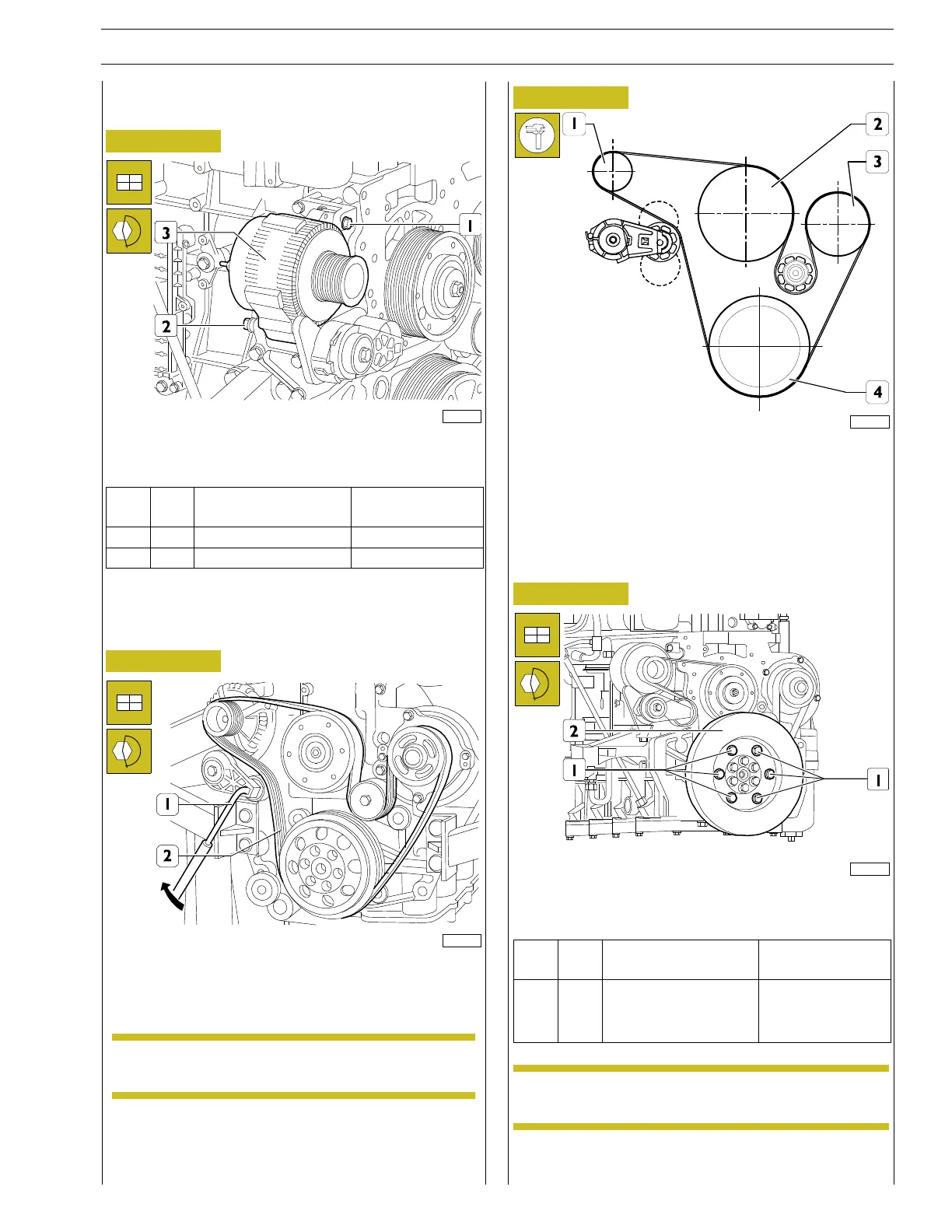
Figure 232
221083
Fit the alternator (3) and tighten the screws (1, 2) to the torque
indicated in the table.
Ref.
No. Description
Tightening
torques
(1) 1 M8x1.25 screw 24.5 ± 2.5 Nm
(2) 1 Screw M10x1.5 44 ± 4 Nm
Alternator/water pump
drive belt assembly
Figure 233
166728
To fit the belt (2) use suitable equipment to adjust the belt
tensioner (1) in the direction indicated by the arrow in the fi-
gure.
NOTE Belt tensioner is of automatic type; therefore,
further adjusting is not provided after mounting.
Figure 234
108844
1 Alternator - 2 Electromagnetic connector -
3 Water pump - 4 Crankshaft
Upon assembly, check the correct installation as shown in the
figure.
Damper flywheel installation
Figure 235
221082
Fit the flywheel damper (2) onto the head and tighten the fa-
stening screws (1) to the torque shown in the table.
Ref.
No. Description
Tightening
torques
(1) 6
Screws M14X2
Step 1 70 Nm
Step 2 50˚
NOTE Before fitting, lubricate the screw thread (1) with
engine oil.