86
SECTION 6 - GENERAL MECHANICAL OVERHAUL
CURSOR SERIES
Base - 03/2015 Print P4D32C006 E
Figure 206
114287
Take the cylinder whose clearance has to be adjusted into the
combustion phase; the valves of this cylinder are closed while
they balance the symmetric cylinder valves.
NOTE Thecorrespondenceofthe symmetrical cylin-
dersis1-6,2-5and3-4.
In order to carry out these operations correctly, follow the indi-
cations below in accordance with the indications in the table.
Using a box wrench, loosen the nut (1) locking the adjustment
screw.
Insert the feeler gauge blade (3) corresponding to the operating
clearance indicated in the table “Data and assembly clearance”
in SECTION 7 - Technical specifications.
Use a suitable wrench to screw or unscrew rocker arm (2) adju-
sting screw.
Check that the blade of the feeler gauge (3) can slide with a light
amount of friction.
Lock the nut (1) holding the adjustment screw still.
To carry out the adjustments stated above, the sequence shown
in the table is mandatory.
FIRING ORDER 1-4-2-6-3-5
Start and rotation in
theenginedirection
Balancing
cylinder
valves no.
Adjust valve
clearance for
cylinder no.
1and6atT.D.C. 6 1
120 degree of angle [˚] 3 4
120 degree of angle [˚] 5 2
120 degree of angle [˚] 1 6
120 degree of angle [˚] 4 3
120 degree of angle [˚] 2 5
NOTE Check during each rotation phase, the accuracy
of the position by using the specific pin and
inserting it into the hole marked with a notch on
the flywheel corresponding to the position of
the pistons.
ASSEMBLY OF ENGINE AT BENCH
(COMPONENTS AT THE TOP PART 3)
Tappet cover assembly
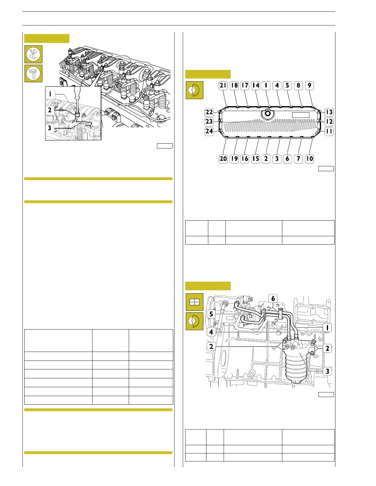
Figure 207
221122
Position the cover and insert all the screws.
Replace the screws in the sequence 1-10-20-21-9 and then in
the sequence shown in the figure until contact.
Tighten the screws 1-24 in the sequence shown to the prescri-
bed torque.
Ref.
No. Description
Tightening
torques
(1 - 24) 24 Screws M6x1 8.5 ±1.5 Nm
ASSEMBLY OF ENGINE AT BENCH
(COMPONENTS AT THE INTAKE SIDE)
Fuel filter assembly
Figure 208
225014
Position the fuel filter together with the support (3), tighten the
screws (2) to the prescribed torque, connect the fuel inlet (4)
and outlet (1) pipes onto the filter support
Ref.
No. Description
Tightening
torques
(2) 4 M8x1.25 24.5 ± 2.5Nm
(1,4) 2 Fittings M18x1.5 37 ± 3Nm