94
SECTION 6 - GENERAL MECHANICAL OVERHAUL
CURSOR SERIES
Base - 03/2015 Print P4D32C006 E
Removing the engine from the rotating stand
Remove the engine from the rotating stand 99361036 and
remove the brackets securing the engine 99361036.
ENGINE ASSEMBLY
Asembly of bracket interference components
Assembly of the air compressor input point
Figure 236
224057
Fittheaircompressorinputtap(2)andtightenthescrews(1)
to the torque indicated in the table.
Ref.
No. Description
Tightening
torques
(1) 3 Screws M12 X 1.75 74 ± 8 Nm
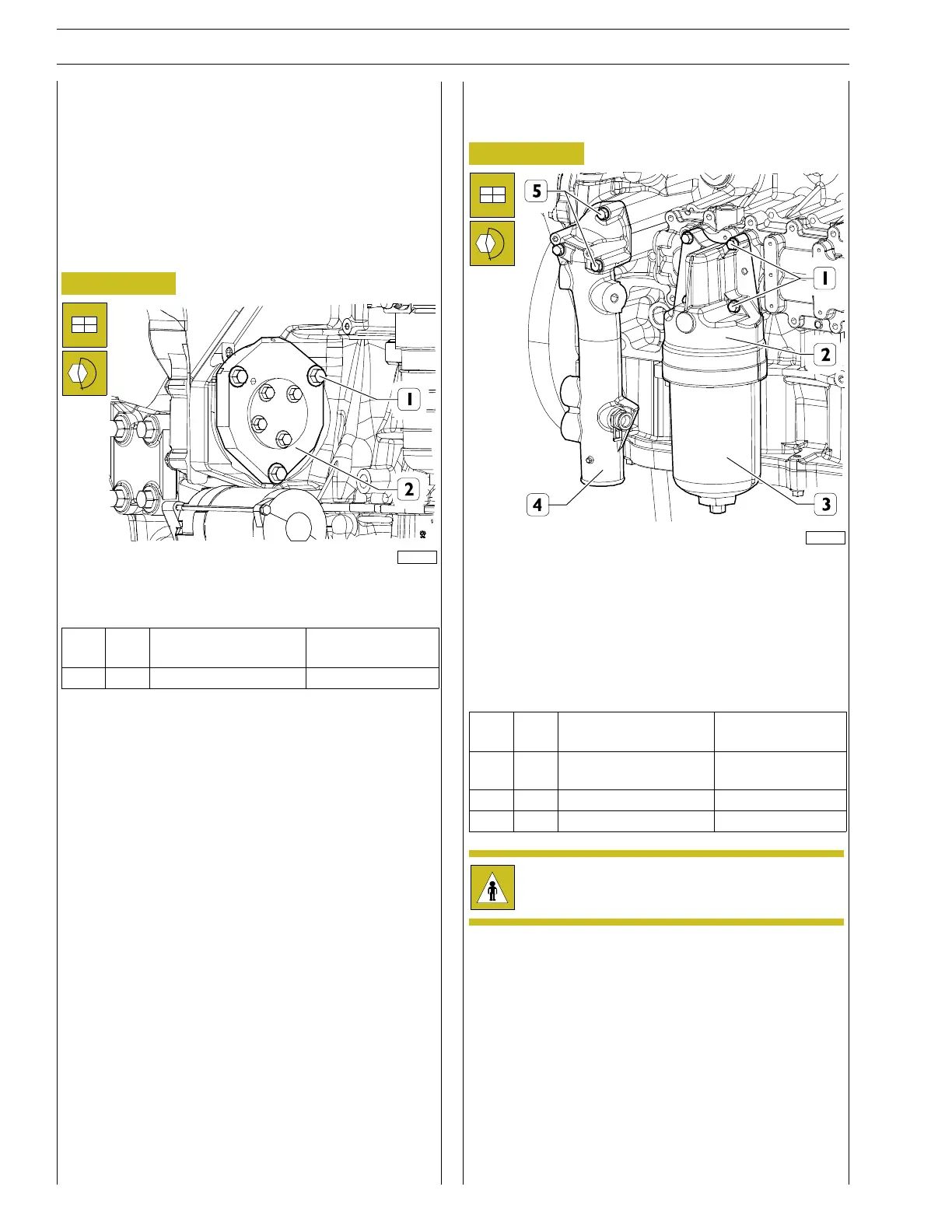
Assembly of the oil filter with relative support and
water inlet pipe to crankcase
Figure 237
224061
Fit the water inlet pipe to the crankcase (4) together with the
new gasket and tighten the screws (5) to the torque indicated
in the table.
Fit the engine oil filter mount (2) together with the new gasket
and tighten the screws (1) to the torqueindicatedinthetable.
Fit the filter element of the oil filter (3) onto its support (2) and
tighten it to the torque indicated in the table.
Ref.
No. Description
Tightening
torques
(1) 4
Screws M8 X 1.25 X
65
24.5 ± 2.5 Nm
(3) 1 - 60 ± 5 Nm
(5) 3 M8 x 1.25 screws 34.5 ± 3.5 Nm
Avoid skin contact with the engine oil: in case of
contact, wash thoroughly with water.