14
SECTION 6 - GENERAL MECHANICAL OVERHAUL
CURSOR SERIES
Base - 03/2015 Print P4D32C006 E
Timing gear cover removal
Figure 29
225017
Remove the timing sensor (1)
Unscrew the screws (2) and remove the distribution cover (3).
Ref.
No. Description
(1) 1 M6 X 12
(2) 21 ScrewsM6X1.0X25
DISASSEMBLY OF ENGINE AT BENCH
(COMPONENTS AT THE TOP
PART 1)
Removal of head cover
Figure 30
224079
Unscrew and remove the pressure sensor (1).
Unscrew the fastening screws (2) and remove the head cover
(3).
Ref.
No. Description
(1) 1 M10 X 1
(2) 24 M6 X 1
DISASSEMBLY OF ENGINE AT BENCH
(COMPONENTS AT THE INTAKE SIDE
PART 2)
Fuel filter removal
Figure 31
225014
Unlock the cable ties (6).
Unscrew the fittings, dsconnect and remove the fuel inlet (4)
and outlet (1) pipes from the high pressure pump (5) and the
fuel filter (3).
Unscrew the screws (2) and remove the oil filter housing
together with the support (3).
Ref.
No. Description
(1, 4) 4 Fitting M18 X 1.5
(2) 4 M8 x 1.25 screws
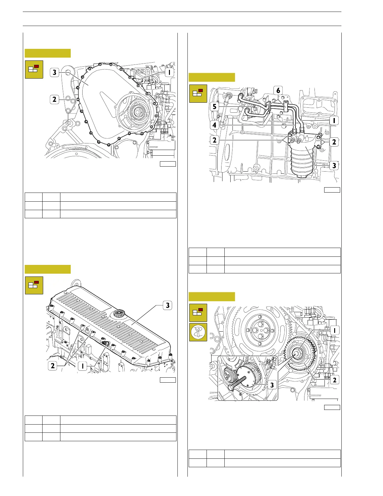
High pressure pump removal
Figure 32
221102
Undo the nut (1).
Apply thetool to extract the high pressure pump gear
99366198 (3) and remove the high pressure pump control
gear (2).
Ref.
No. Description
(1) 1 Nut M24 X 1.5