SECTION 6 - GENERAL MECHANICAL OVERHAUL
91
CURSOR SERIES
Print P4D32C006 E Base - 03/2015
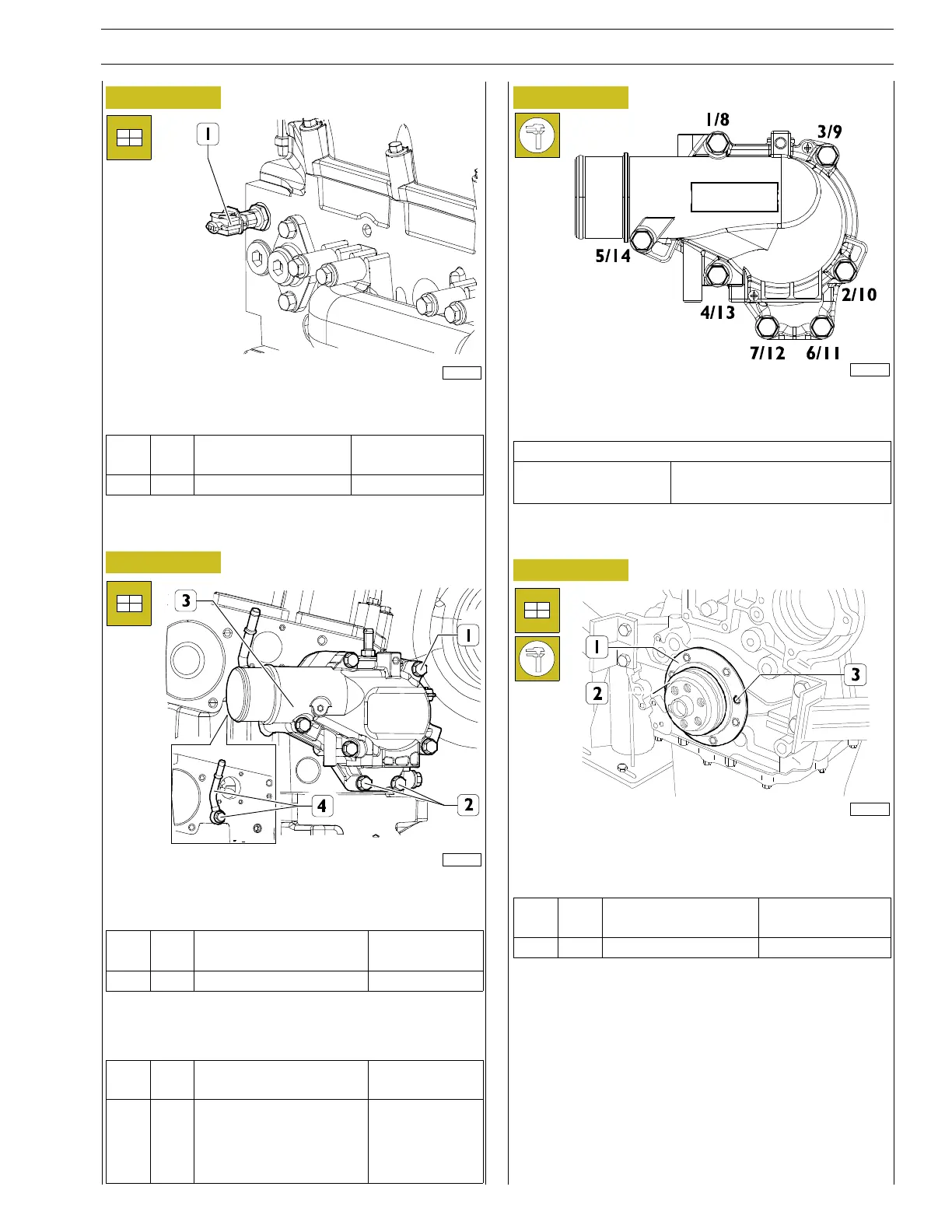
Figure 224
225021
Fit the coolant sensor (1) and tighten to the torque indicated
in the table.
Ref.
No. Description
Tightening
torques
(1) 2 M12 X 1.5 20 ± 5 Nm
Thermostat case assembly
Figure 225
224067
Mount the degasing pipe (4) and tighten the screw to the tor-
que specified in the table.
Ref.
No. Description
Tightening
torques
(4) 1 M10 X 1.5 25 ± 2.5 Nm
Fit the thermostat case (3) with a new gasket and tighten the
fastening screws (1, 2) to the prescribed torque according to
the sequence indicated in the next figure.
Ref.
No. Description
Tightening
torques
(1-2)
5 Screws M8 X 1.25 X 100
2 Screws M8 X 1.25 X50
Step 1 30 ± 3 Nm
Step 2 30 ± 3 Nm
Figure 226
155929
Tighten the fastening screws following the order indicated in
the table.
Tightening sequence
Step 1 1-2-3-4-5-6-7
Step 2 8-9-10 -11-12-13-14
Crankshaft front gasket installation
Figure 227
60563
Using the centring ring 99396035 (2), check the exact position
of the cover (1), otherwise act as necessary and tighten the sc-
rews (3) to torque stated in the table.
Ref.
No. Description
Tightening
torques
(3) 8 M8 X 1.25 X 16 25 ± 2.5 Nm