6
SECTION 2 - OPERATING DIAGRAMS
CURSOR SERIES
Base - 03/2015 Print P4D32C006 E
Figure 4
180253
1 Plunger (2x) - 2 CP5 gear plungers - 3 Flow regulator
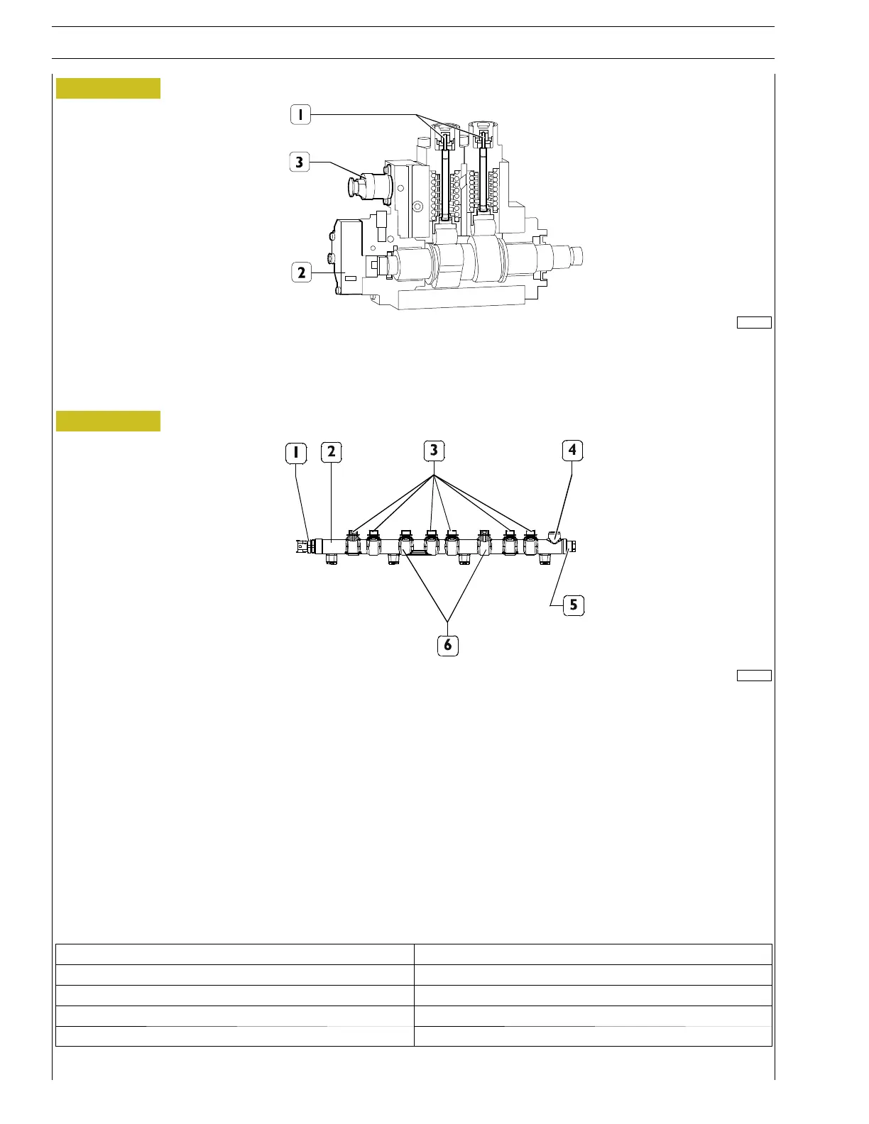
Hydraulic accumulator (rail)
Figure 5
180254
1 Pressure sensor - 2 Rail - 3 Pipes to injectors - 4 Fuel return - 5 Overpressure valve -
6 Fuel inlets from high pressure pump
The rail volume is of reduced sizes to allow a quick pressurisation at startup, at idle and in case of high flow-rates.
It anyway has enough volume as to minimise pulsations caused by injectors openings and closings and by the high-pressure pump
operation.
This function is further enabled by a calibrated hole being set downstream of the high-pressure pump.
Some calibrated holes have been made in the retaining fittings of the high pressure pipes, with the function of damping the oscilla-
tions in pressure generated by the opening of the injectors and the plungers of the high pressure pump.
A fuel pressure sensor (1) is screwed to the rail.
The signal sent by this sensor to the electronic control unit is a feed-back information, depending on which the rail pressure value
is checked and, if necessary, corrected.
Specifications
Technical data
Nominal rail volume 28.6 cm
3
Inner diameter 9mm
Nominal pressure 2,200 bar
Operating temperature -40 to 140 ˚C