76
SECTION 6 - GENERAL MECHANICAL OVERHAUL
CURSOR SERIES
Base - 03/2015 Print P4D32C006 E
Figure 184
221116
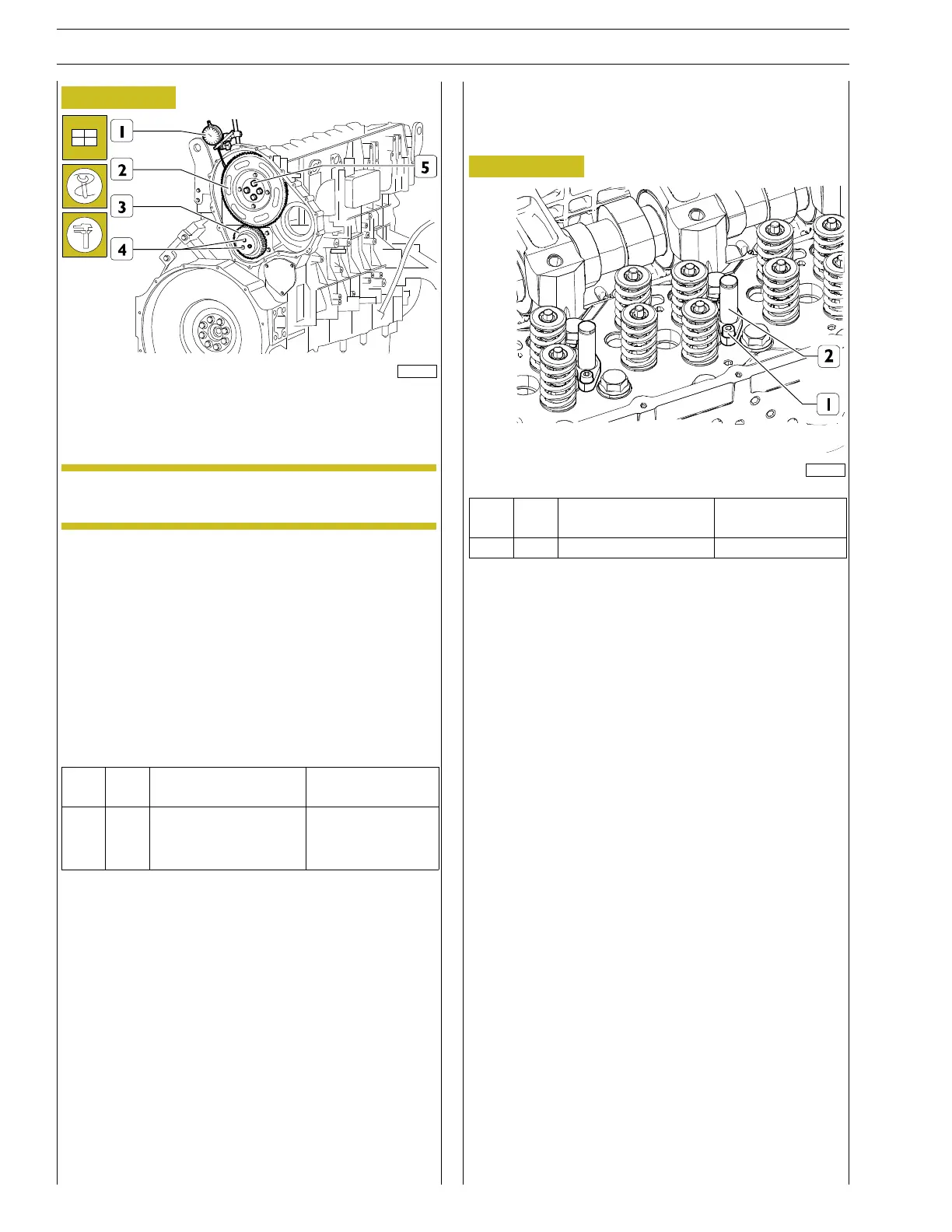
Position the gear (2) on the camshaft so that the 4 slots are
centred with the holes for fixing the camshaft, without fully loc-
king the screws (5).
NOTE Lubricate the screws (5) with engine oil before
assembly.
With a magnetic dial gauge (1) check clearance between the
gears (2, 3), which must be between 0.074 - 0.195 mm, other-
wise adjust the clearance as indicated below:
Loosen the screws (4) securing the transmission gear (3).
Loosen the connecting rod fixing screw , move the connecting
rod in order to obtain the required clearance.
Lock the screw securing the connecting rod and the screws (4)
securing the transmission gear to the prescribed torque.
Tighten the camshaft drive gear fastening screws (5) to the tor-
que prescribed.
Ref.
No. Description
Tightening
torques
(5) 4
ScrewsM14X4X60
Step 1 20 ± 3 Nm
Step 2 60˚
Assembling the engine brake cylinders
Fit the engine brake cylinders (2) onto the cylinder head and
tighten the screws (1) to the torque indicated in the table.
Figure 185
227748
Ref. No. Description
Tightening
torques
(1) 12 M8 X 1.25 X 20 25 ± 2.5 Nm