48
SECTION 6 - GENERAL MECHANICAL OVERHAUL
CURSOR SERIES
Base - 03/2015 Print P4D32C006 E
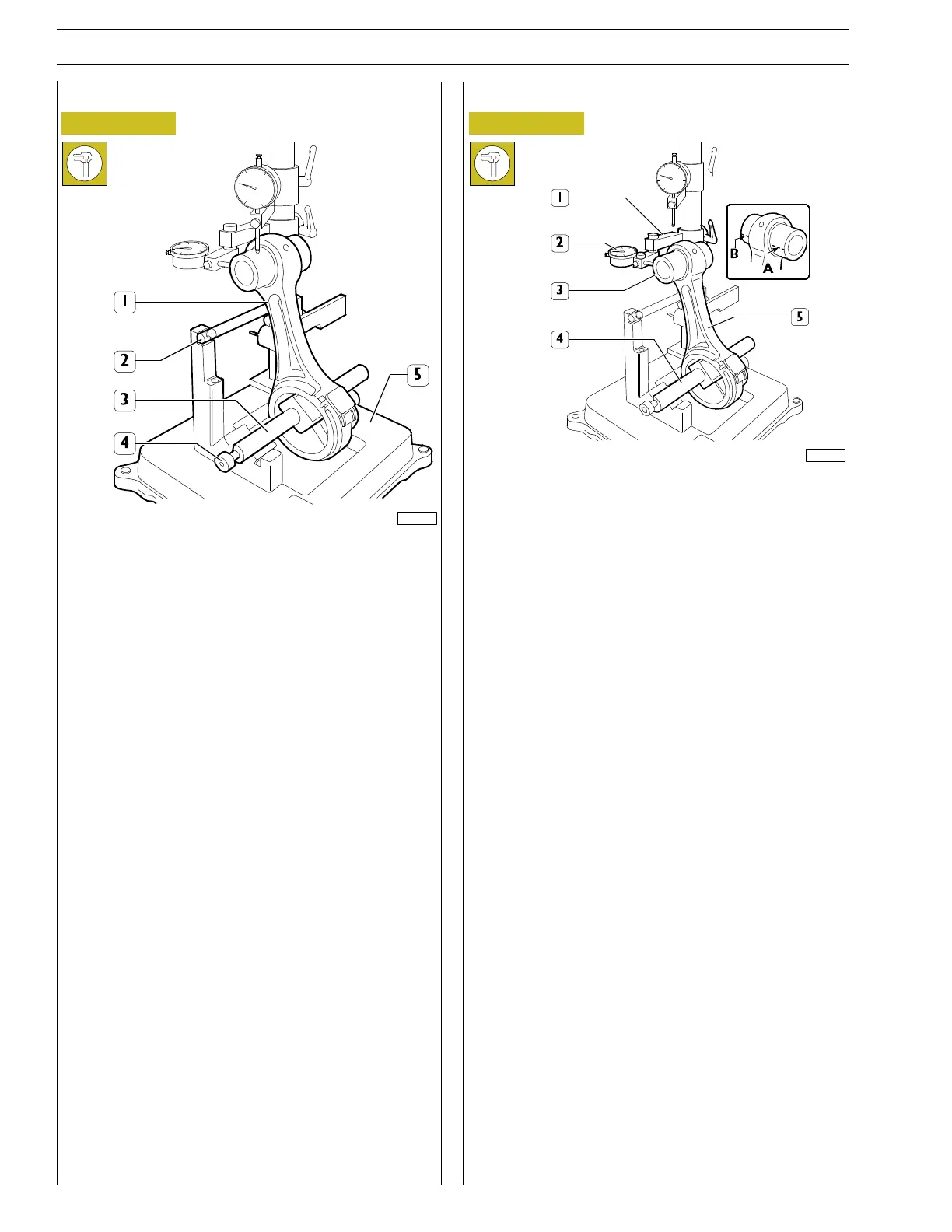
Axis alignment check
Figure 104
61696
Check the connecting rods axes for parallelism (1) using a
suitable device (5) and proceeding as follows.
Fit the connecting rod (1) on the spindle of the tool (5) and
lock it with the screw (4).
Set the spindle on the on the V prisms resting the connecting
rod 1 on the stop bar (2).
Torsion check
Figure 105
61694
Check the torsion of the connecting rod (5) by comparing two
points (A and B) of the pin (3) on the horizontal plane of the
axis of the connecting rod.
Position the mount (1) of the dial gauge (2) so that this
pre-loads by approx. 0.5 mm on the pin (3) at point A and zero
the dial gauge (2). Move the spindle (4) with the connecting
rod (5) and compare any deviation on the opposite side B of
the pin (3): the difference between A and B must be no
greater than 0.08 mm.