SECTION 6 - GENERAL MECHANICAL OVERHAUL
13
CURSOR SERIES
Print P4D32C006 E Base - 03/2015
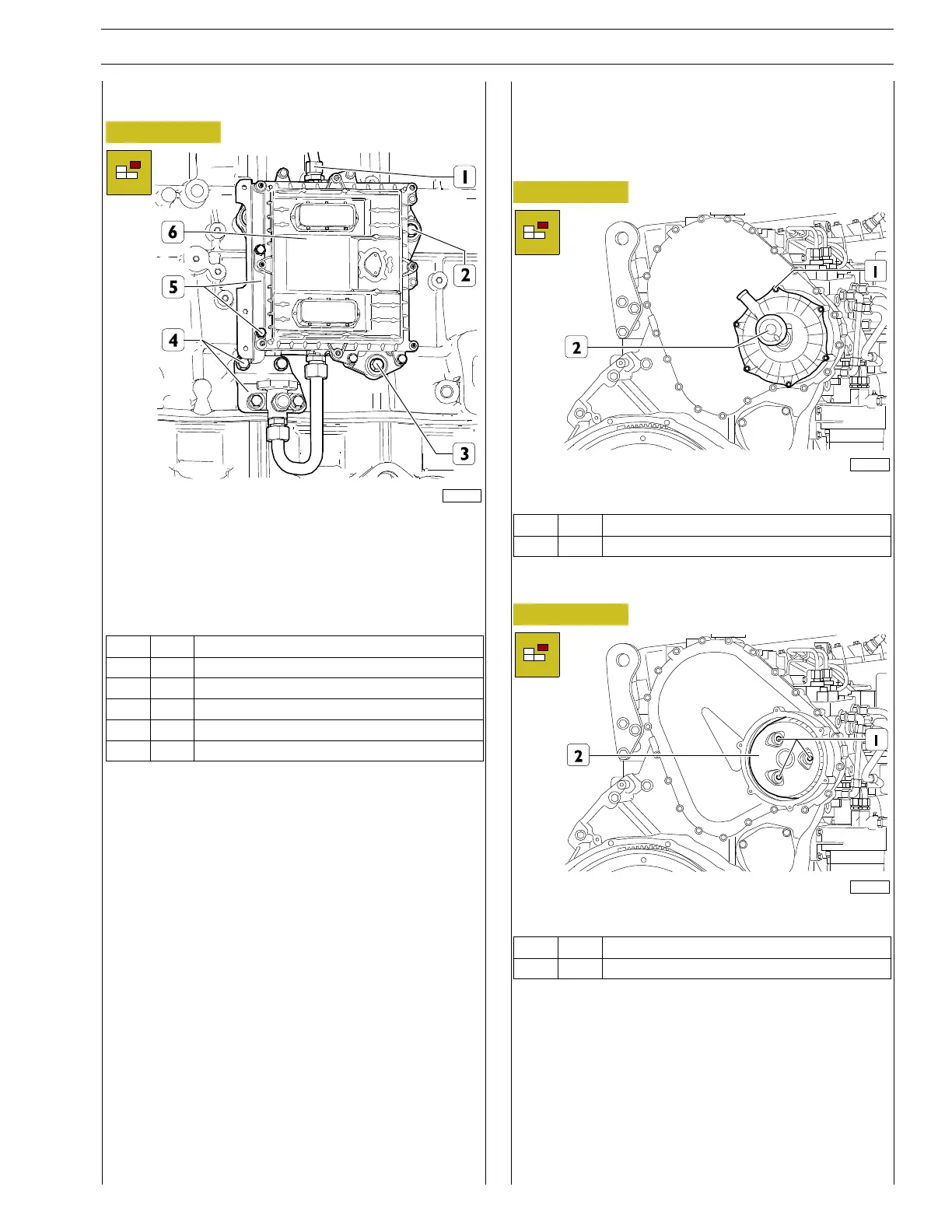
Engine control unit removal
Figure 26
224072
Unscrew the screws and remove the bracket (5).
Unscrew fittings (1) and disconnect the low pressure fuel pipes
from the control unit.
Unscrew the screws of the control unit mount (2, 3), the scre-
ws of the bracket (4) and remove the engine control unit (6).
Ref.
No. Description
(1) 1 Fitting M22 X 1.5
(2) 2 Screws M8 X 1.25 X 60
(3) 1 Screws M8 X 1.25 X 45
(4) 2 Screws M8 X 1.25 X 16
(5) 2 ScrewsM6X1X25
DISASSEMBLY OF ENGINE AT BENCH
(COMPONENTS AT THE REAR SIDE
PART 1)
Blow-by case removal
Figure 27
221097
Unscrew the screws (1) and remove the blow-by case (2).
Ref.
No. Description
(1) 6 ScrewsM6X1X25
Blow-by filter removal
Figure 28
221098
Unscrew the screws (1) and remove the blow-by filter (2).
Ref.
No. Description
(1) 3 ScrewsM6X1X40