SECTION 6 - GENERAL MECHANICAL OVERHAUL
53
CURSOR SERIES
Print P4D32C006 E Base - 03/2015
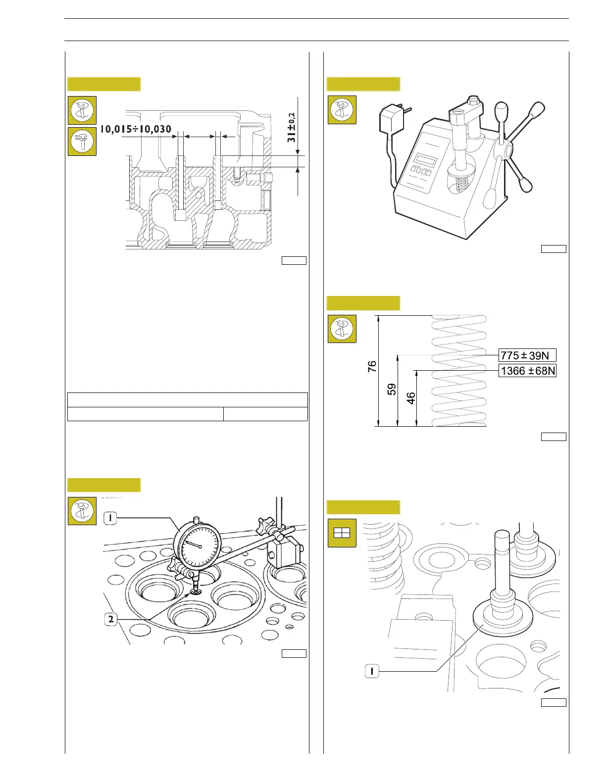
Replacing the valve guides
Figure 117
163815
* = Measurement to be obtained after driving in the valve
guides
The valve guides are removed with the drift 99360143.
Assembly is carried out with the drift 99360296 equipped with
tool 99360143.
It determines the exact position of the valve guides fitted in
the cylinder head; if they are not available, you need to drive
the valve guides into the cylinder head so they protrude by a
value equal to the one given below .
Technical data
Valve guide standout 30.80 - 31.2 mm
After driving in the valve guides, smooth their holes with
sleeker 99390330.
Checking protrusion of injectors
Figure 118
47585
Check injector protrusion (2) using a dial gauge (1).
Valve spring check
Figure 119
70000
Before fitting, the flexibility of the valve springs has to be
checked using a suitable device.
Figure 120
108842
Compare the load and elastic deformation data with that of
the new springs indicated in the figure.
Valve assembly
Figure 121
193982
Lubricate the valve stem and insert the valves in the respective
valve guides; fit the lower plates (1).