SECTION 5 - REMOVAL - REFITTING OF THE MAIN ENGINE COMPONENTS
15
CURSOR SERIES
Print P4D32C006 E Base - 03/2015
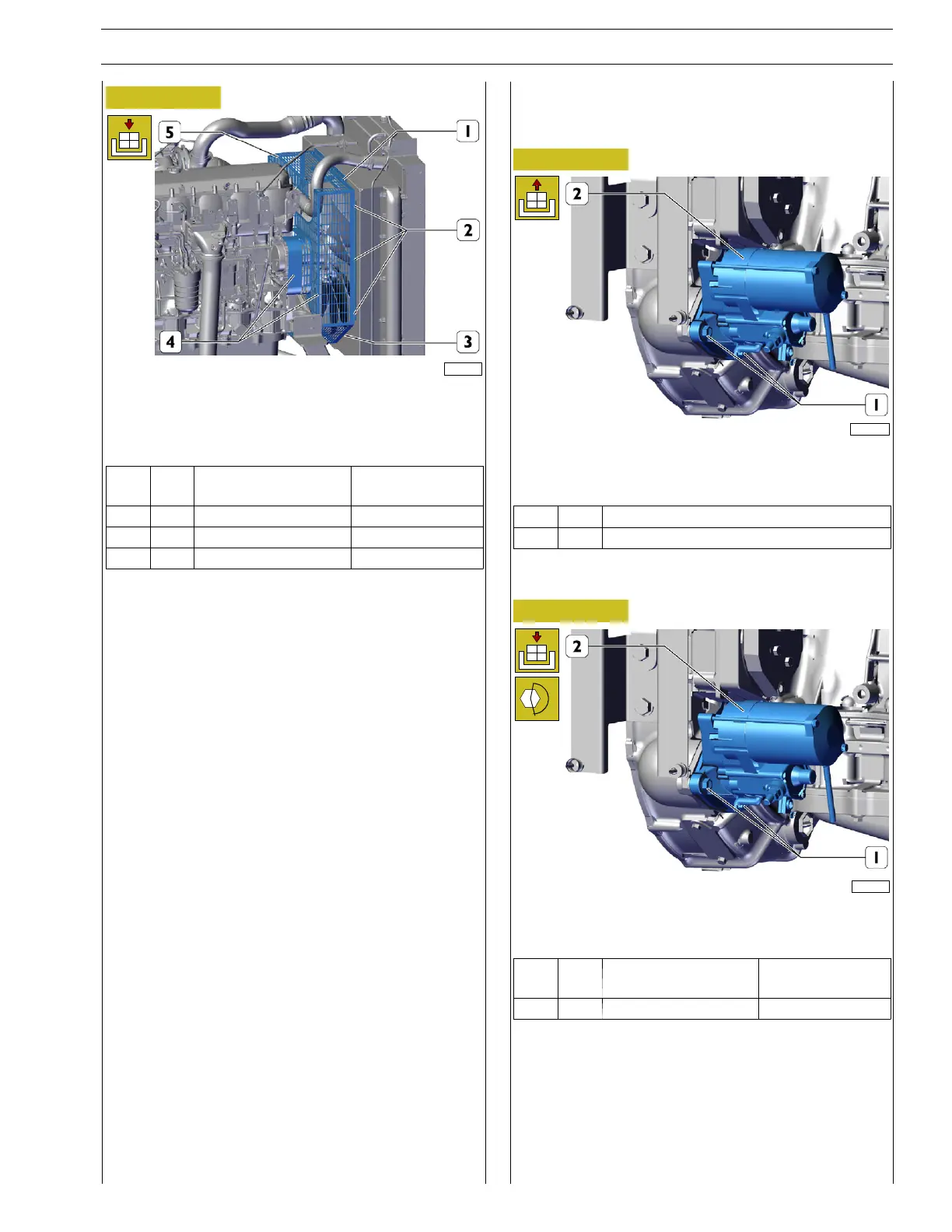
Figure 36
227753
Laterally install the fan protection grilles (4) and (5).
Tighten and lock the top screws (1) the bottom screw (3) and
side screws (2) to the torque in the table.
Ref.
No. Description
Tightening
torques
(1) 5 Screws M8x1.25x20 18 ± 4 Nm
(2) 6 Screws M8x1.25x20 18 ± 4 Nm
(3) 1 Screw M8x1.25x20 18 ± 4 Nm
STARTER MOTOR REMOVAL-REFITTING
Removal
Figure 37
227759
Remove the nuts (1) from the studs.
Remove the electric starter motor (2).
Ref.
No. Description
(1) 3 Nuts M12 X 1.75
Refitting
Figure 38
227759
Fit the starter motor (2) and tighten the nuts (1) onto the
captive screws to the torque indicated in the table.
Ref.
No. Description
Tightening
torques
(1) 3 Nuts M12 X 1.75 74 ± 8Nm