92
SECTION 6 - GENERAL MECHANICAL OVERHAUL
CURSOR SERIES
Base - 03/2015 Print P4D32C006 E
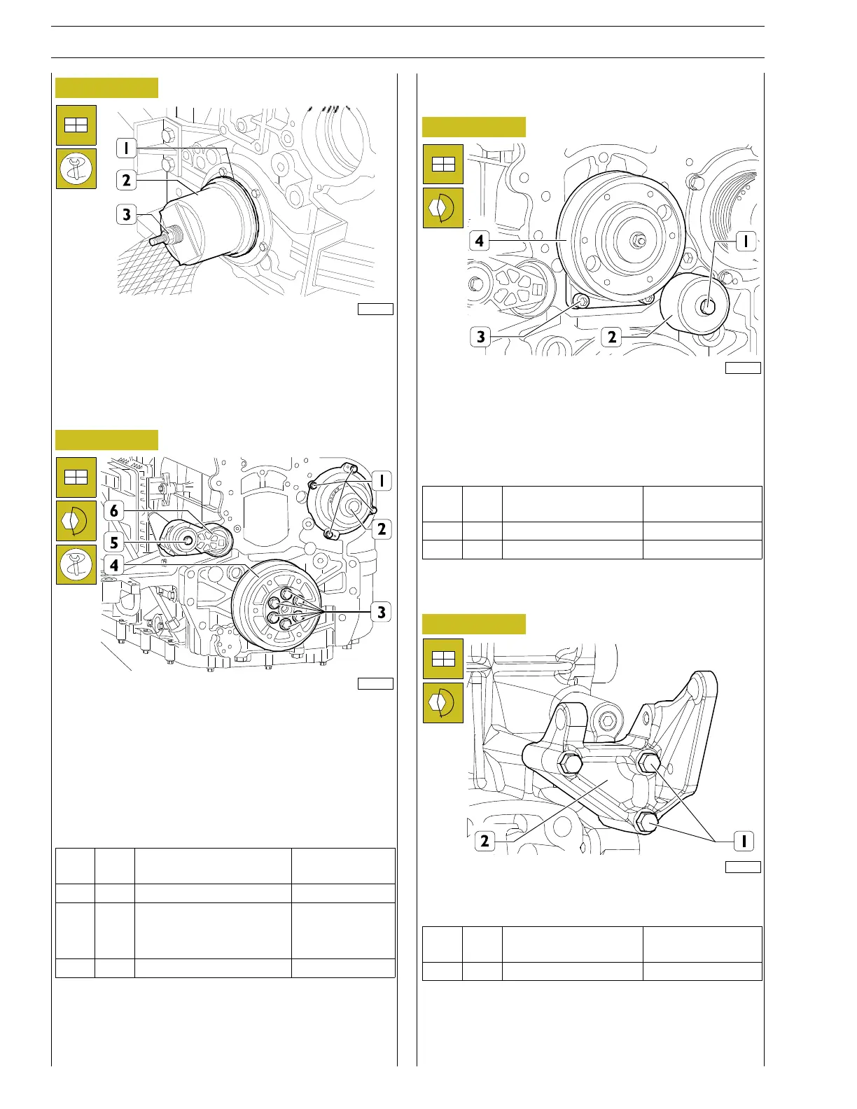
Figure 228
60564
Position the sealing gasket (1) onto the crankshaft, fit the keying
device 99346250 (2) and while tightening the nut of the tool
(3) drive in the sealing gasket (1).
Assembly of auxiliary parts
Figure 229
225016
Block rotation of the flywheel with the tool 9936035I.
Mount the automatic belt tensioner (6) and the nuts (5) to the
torque indicated in the table.
Fit the crankshaft pulley (4) and tighten the screws (3) to the
torque indicated in the table.
Fit the water pump (2) together with the new gasket and
tighten the screws (1) to the torque indicated in the table.
Ref.
No. Description
Tightening
torques
(1) 4 Screws M8 X 1.25 X 20 25 ± 2.5 Nm
(3) 6
M14 x 2 screws
Step 1 70 Nm
Step 2 50˚
(5) 1 M10x1.5screw 45 ± 5 Nm
Electromagnetic coupling assembly
Figure 230
225023
Fit the pulley electromagnetic coupling assembly (4) and
tighten the screws of the plate (3) to the torque indicated in
the table.
Mount the fixed belt tensioner (2) and the nuts (1) to the
torque indicated in the table.
Ref.
No. Description
Tightening
torques
(1) 1 Screws M12 X 1.75 105 ± 5 Nm
(3) 5 Screws M12 X 1.75 100 ± 5 Nm
Alternator support assembly
Figure 231
224063
Fit the alternator support (2) and tighten the screws (1) to the
torque indicated in the table.
Ref.
No. Description
Tightening
torques
(1) 3 M10x1.5screws 44 ± 4 Nm