SECTION 6 - GENERAL MECHANICAL OVERHAUL
83
CURSOR SERIES
Print P4D32C006 E Base - 03/2015
Fit tool 99360612 (5) into the flywheel sensor seat (6).
Through the timing sensor, insert the tool for phonic disc ti-
ming on the camshaft 99360613 (2) on the tooth (")recove-
red from the phonic wheel.
If the tool (2) is difficult to fit, loosen the screws (3) and direct
the phonic wheel (1) properly so as to position the tool (2)
on the tooth correctly.
Tighten the screws (3).
Ref.
No. Description
Tightening
torques
(3) 4 M8X1.25 screws 24.5 ± 2.5 Nm
Remove tools 99360612 and 99360613.
ASSEMBLY OF ENGINE AT BENCH
(COMPONENTS AT THE INTAKE SIDE)
High pressure pump assembly
Bring the flywheel to 36˚ before TDC of the first cylinder.
NOTE This position can be obtained by turning the en-
gine flywheel in the opposite direction to the
operating direction in the 30˚ position marked
by THREE notches (4) and continuing to turn
the flywheel in the same direction until reaching
thenexthole(by6˚).
If the engine flywheel does not have 3 notches,
to identify the reference hole simply: turn the
flywheel in the opposite direction to the opera-
ting direction until reaching the position marked
with 2 notches (54˚ before cyl. 1 T.D.C.); conti-
nue rotating in the engine operating direction
for 3 holes (remember that each hole corre-
sponds to a flywheel rotation of 6˚).
Insert the specific tool 99360612 through the seat of the fly-
wheel sensor into the corresponding hole on the flywheel.
Figure 200
221104
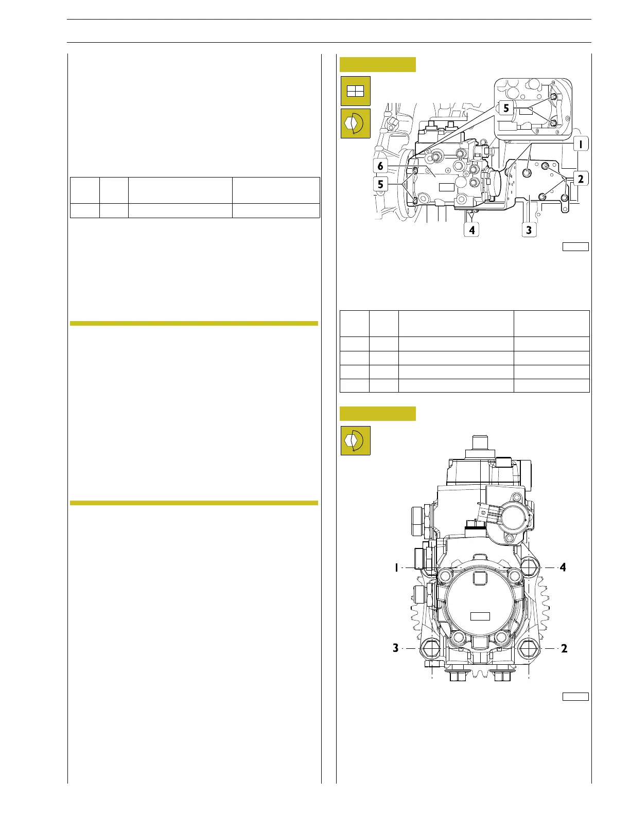
Position the bracket (3) and tighten the screws (1,2).
Position the high pressure pump (6) and tighten the screws (4,
5) to torque shown in the table.
Ref.
No. Description
Tightening
torques
(1) 2 Screws M10 X 1.5 X 20 37.5 ± 5 Nm
(2) 3 Screws M8 X 1.25 X 20 24.5 ± 2.5 Nm
(4) 2 Screw M12 X 1.75 X 30 32.5 ± 2.5 Nm
(5) 4 Screws M12 X 1.5 37.5 ± 2.5 Nm
Figure 201
225012
Observe the order of tightening indicated in the diagram.