18
SECTION 6 - GENERAL MECHANICAL OVERHAUL
CURSOR SERIES
Base - 03/2015 Print P4D32C006 E
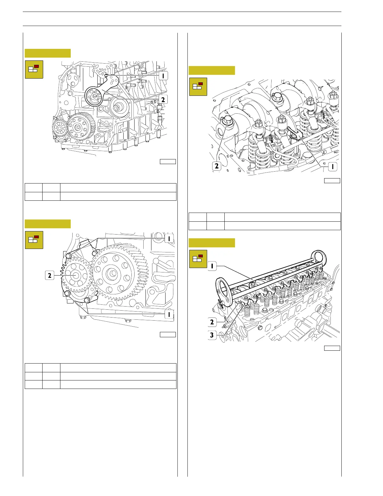
Connecting rod removal
Figure 44
221112
Unscrew the screw (1) and remove the connecting rod (2).
Ref.
No. Description
(1) 1 Screws M8 X 1.25 X 16
Disassembling the oil pump
Figure 45
221113
Unscrew the fastening screws (1) and remove the oil pump
(2).
Ref.
No. Description
(1) 1 Screws M8 X 1.25 X 35
(1) 3 Screws M8 X 1.25 X 70
DISASSEMBLY OF ENGINE AT BENCH
(COMPONENTS AT THE TOP PART 2)
Rocker arm shaft removal
Figure 46
227745
Release the retainer springs of the engine brake (1).
Unscrew the screws (2) securing the rocker arm shaft.
Ref.
No. Description
(2) 7 ScrewsM16X1.5X76
Figure 47
224083
Use the specified tool 99360553 (1) on the rocker arm shaft
(2) and remove the shaft (2) from the cylinder head. Remove
the crosspieces (3) from the cylinder head.