SECTION 6 - GENERAL MECHANICAL OVERHAUL
67
CURSOR SERIES
Print P4D32C006 E Base - 03/2015
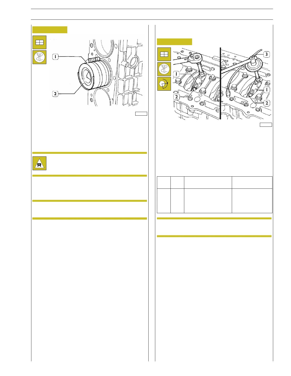
Figure 155
60616
Using the clamp to introduce the piston into the cylinder liner
99360603 (1), fit the piston-connecting rod assembly (2) into
the cylinder liners following the diagram in the previous Figure.
Check that the number of each connecting rod corresponds
to the cap coupling number .
During assembly, make absolutely sure that the
connecting rod does not hit against the cylinder
liner walls.
Check that the ideogram stamped on the piston crown faces
the engine flywheel; or the recess in the piston skirt matches
the position of oil nozzles .
NOTE The pistons are supplied as class A spare parts
and can also be fitted in class B cylinder liners.
Crankpin fitting clearance check
Figure 156
α
47594
Connect the connecting rods to the relevant journals of the
crankshaft, placing a length of calibrated wire on the journals.
mount the connecting rod caps (1) together with half-bearings;
tighten the screws (2) securing the connecting rod caps to the
prescribed torque.
Use tool 99395216 (3) to additionally tighten the screws to
the prescribed angle.
Ref.
No. Description
Tightening
torques
(2) 12
Screws fixing connec-
ting rod cap
M14 X 2
Step 1 70 Nm
Step 2 60˚
NOTE The thread of the screws (2), before assembly,
has to be lubricated with engine oil.
Remove the caps and check the clearance by comparing the
width of the calibrated wire with the scale calibration on the
envelope containing the wire.
Upon final assembly: check the diameter of the threading of the
screws (2) which must not be less than 13.4 mm, otherwise
replace the screw;
lubricate the crankpins and big end bearings; tighten the screws
(2) as described above.