75532
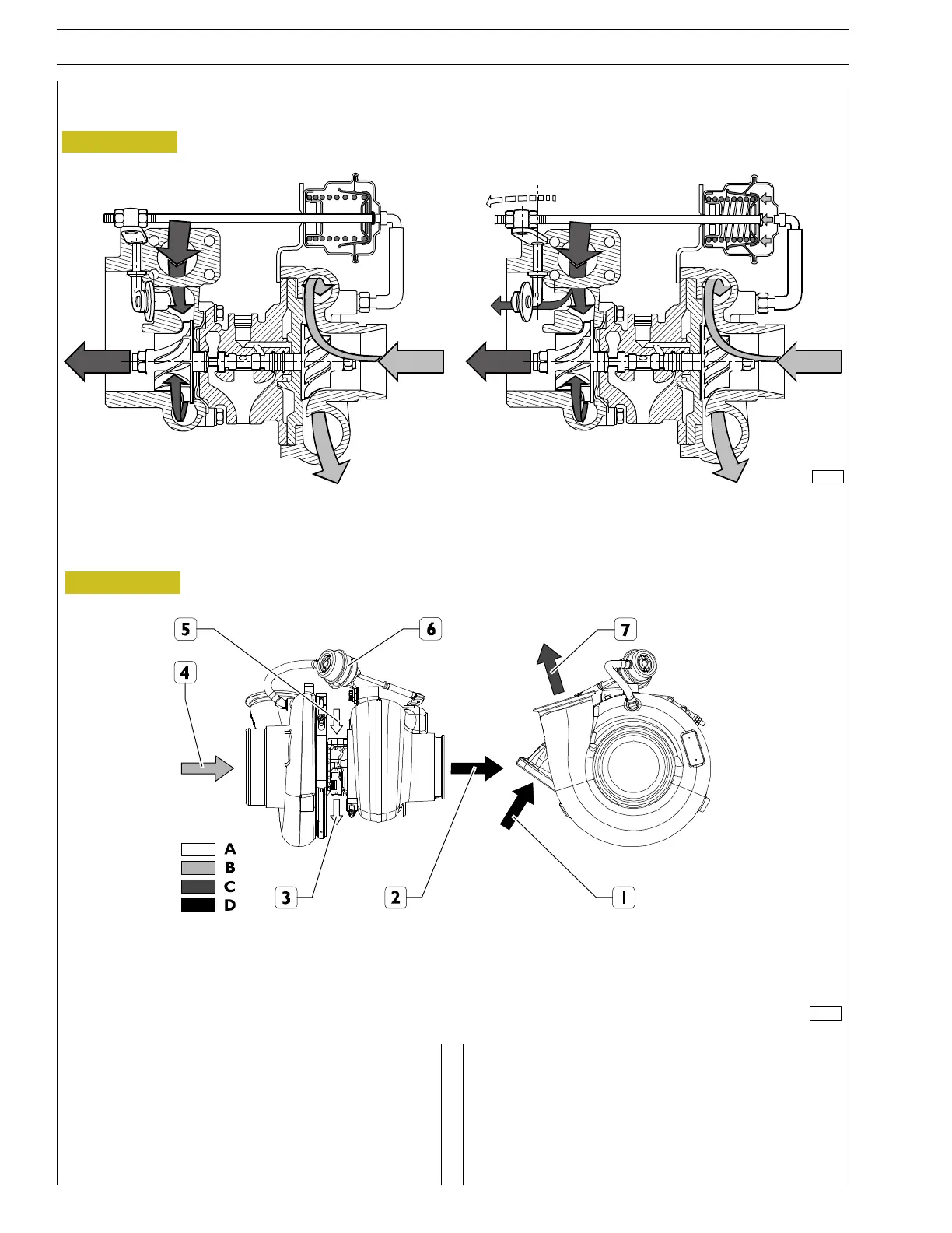
Essentially this consists of:
- a central body in which a shaft is housed, supported by
bushings, the ends of which are connected to: the
turbine rotor and the compressor rotor;
- a turbine body and a compressor body fitted at the ends
of the centre body;
- an pressure limiter valve fitted on the turbine casing. Its
function is to choke the exhaust gas outlet (detail B),
sending a portion of the exhaust gas directly into the
exhaust pipe when the turbo charging pressure down
from the turbocharger reaches a calibrated value;
221065
Figure 26
Figure 27
turbocharger
A. CLOSED THROTTLE VALVE B. THROTTLE VALVE OPEN
A. Lubricant oil - B. Uncompressed air - C. Compressed air - D. Exhaust gas
1. Exhaust gas intake from manifold - 2. Exhaust gas outlet (to outside) - 3. Oil outlet - 4. Air inlet - 5. Oil inlet -
6. Pneumatic actuator - 7. Compressed air outlet
20
SECTION 2 - OPERATING DIAGRAMS
CURSOR SERIES
Base - 03/2015 Print P4D32C006 E