16
SECTION 6 - GENERAL MECHANICAL OVERHAUL
CURSOR SERIES
Base - 03/2015 Print P4D32C006 E
DISASSEMBLY OF ENGINE AT BENCH
(COMPONENTS AT THE REAR SIDE
PART 2)
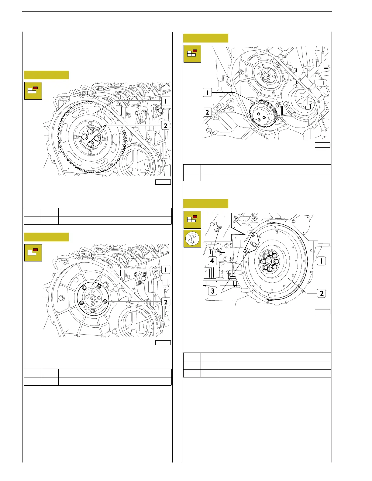
Timing gear removal
Figure 36
221105
Unscrew the screws (2) and remove the gear (1) fitted with
phonic wheel.
Ref.
No. Description
(2) 4 ScrewsM14X4X60
Figure 37
221106
Unscrew the screws (2) and remove the thrust plate (1) and
the sheet gasket.
Ref.
No. Description
(2) 5 Screws M8 X 1.25 X 25
Figure 38
221107
Unscrew the screws (2) and remove the idle gear (1).
Ref.
No. Description
(2) 3 Screws M12 X 1.75 X 110
Flywheel removal
Figure 39
225056
Unscrew the screw and remove the rpm sensor (4).
Using the tool 99360351 to lock the mounted engine flywheel
(3) unscrew the retaining screws (1); then remove the tool (3)
and remove the engine flywheel (2).
Ref.
No. Description
(1) 8 Screws M18 X 1.5 X 72
(4) 1 M6 x 12 screws