SECTION 6 - GENERAL MECHANICAL OVERHAUL
87
CURSOR SERIES
Print P4D32C006 E Base - 03/2015
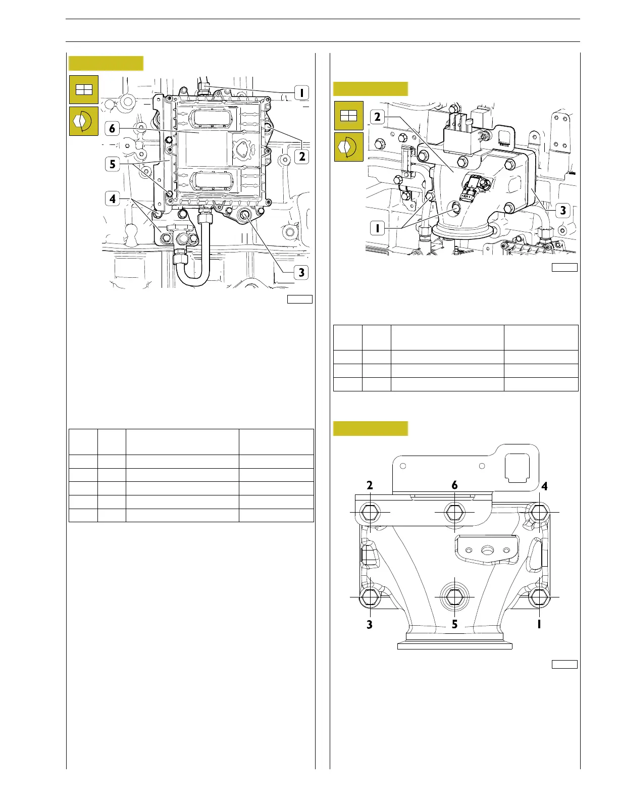
Figure 209
224072
Fit the engine control unit (6) and tighten the screws of the
mount (2, 3) to the torque indicated in the table.
Fit the low pressure pipe bracket and tighten screws (4) to the
torque indicated in the table.
Fit the bracket and tighten screws (5) to the torque indicated
in the table.
Connect the low pressure pipefrom control unit to pump and
tighten fitting (1) to the torque indicated in the table.
Ref.
No. Description
Tightening
torques
(1) 1 Fitting M22 X 1.5 50 ± 5 Nm
(2) 2 Screws M8 X 1.25 X 60 24.5 ± 2.5 Nm
(3) 1 Screws M8 X 1.25 X 45 24.5 ± 2.5 Nm
(4) 2 Screws M8 X 1.25 X 16 24.5 ± 2.5 Nm
(5) 2 ScrewsM6X1X25 8±2Nm
Inlet manifold assembly
Figure 210
225038
Fit the intake manifold (2) together with the engine preheating
resistor (3) and tighten the screws (1) to the to torque stated
in the table.
Ref.
No. Description
Tightening
torques
(1) 3 Screws M10 X 1.5 X 100 50 ± 5 Nm
(1) 2 Screws M10 X 1.5 X 130 50 ± 5 Nm
(1) 1 Screws M10 X 1.5 X 150 50 ± 5 Nm
Tightening sequence
Figure 211
225039