38
SECTION 5 - REMOVAL - REFITTING OF THE MAIN ENGINE COMPONENTS
CURSOR SERIES
Base - 03/2015 Print P4D32C006 E
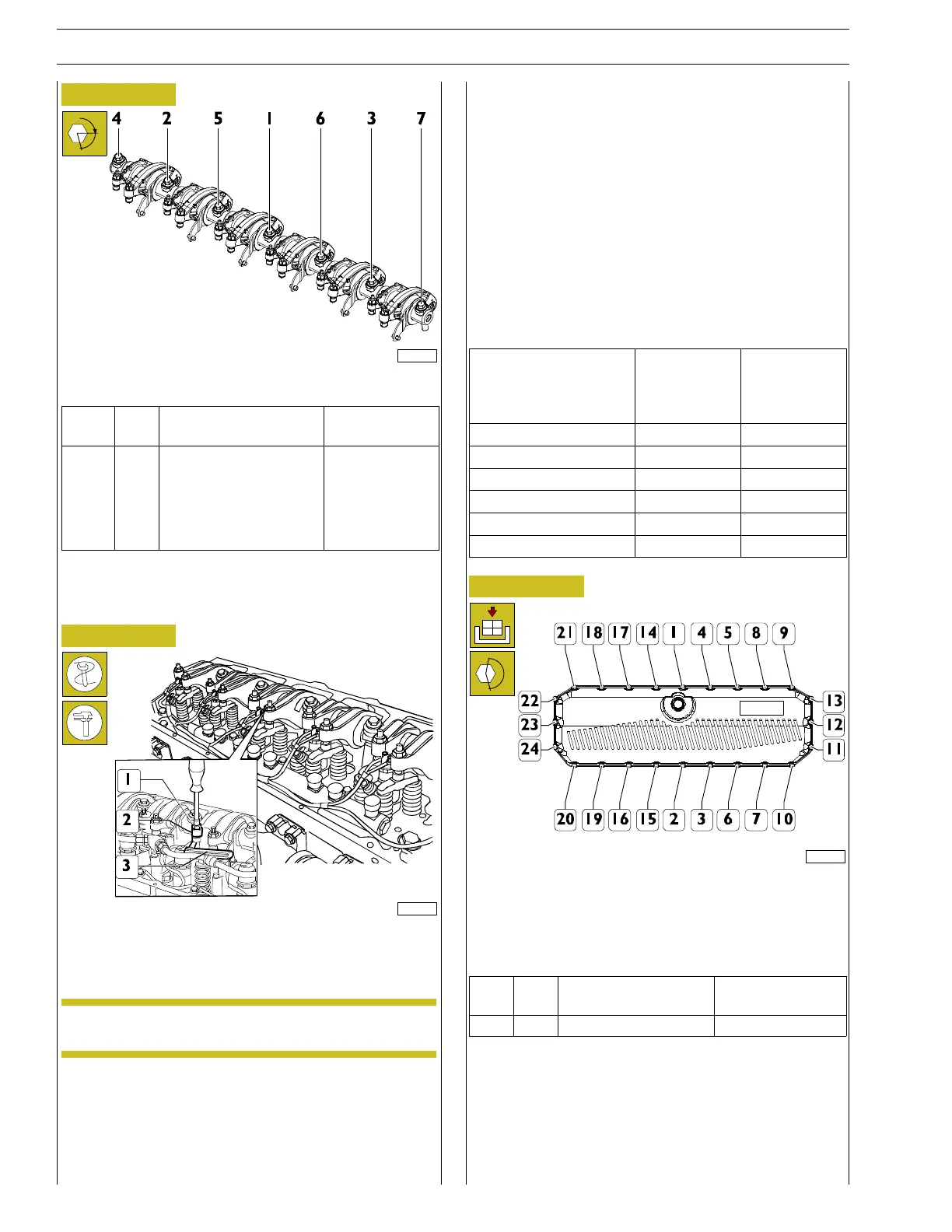
Figure 105
α
227746
Screw the screws in four steps as follows:
Ref.
No. Description
Tightening
torques
(1 - 7) 7
Screws M16 X 1.5 X 76
Step 1 25 Nm
Step 2 60 Nm
Step 3 80 Nm
Step 4 60˚
Tighteningsequence:1-2-3-4-5-6-7
Setting rocker free play
Figure 106
114287
Take the cylinder whose clearance has to be adjusted into the
combustion phase; the valves of this cylinder are closed as they
balance those of the symmetric cylinder.
NOTE The correspondence of the symmetrical cylinders
is1-6,2-5and3-4.
In order to properly operate, follow these instructions and
data specified on the table.
By means of a ratchet spanner, loosen the nut (1) locking the
adjustment screw.
Insert the feeler gauge blade (3) corresponding to the
operating clearance indicated in the table “Data and assembly
clearance” in SECTION 7 - Technical specifications.
Use a suitable wrench to screw or unscrew rocker arm (2)
adjusting screw.
Check that the thickness gauge blade (3) can slide with a slight
friction.
Lock the nut (1) holding the adjustment screw still.
To carry out the adjustments stated above, the sequence
showninthetableismandatory.
Start and rotation in
the
Engine operation
Balancing
Adjusting
clearance
Adjust valve
clearance
Adjusting
clearance
1and6atT.D.C. 6 1
120 degree of angle [˚] 3 4
120 degree of angle [˚] 5 2
120 degree of angle [˚] 1 6
120 degree of angle [˚] 4 3
120 degree of angle [˚] 2 5
Figure 107
221122
Position the cover and new gasket and insert all the screws.
Replace the screws in the sequence 1-10-20-21-9 and then in
thesequenceshowninthefigureuntilcontact.
Tighten the screws (1-24 ) to the torque specified in the table.
Ref.
No. Description
Tightening
torques
(-) 24 M6 x 1 screws 8.5±1.5Nm
Connect the electric connection of engine crankcase pressure
sensor.