22
SECTION 6 - GENERAL MECHANICAL OVERHAUL
CURSOR SERIES
Base - 03/2015 Print P4D32C006 E
Lower crankcase removal
Figure 59
60519
Using an appropriate wrench and the hex wrench unscrew the
screws(1)and(2)andtakeoffthelowercrankcase.
Ref.
No. Description
(1) 14 M18 x 2 screws
(2) 26 Screws M12 X 1.75
NOTE Note down the assembly position of the top
and bottom main half-bearings since, if reusing
them, they will need to be fitted in the position
found upon removal.
Crankshaft removal
Figure 60
47570
Using the tool for lifting the crankshaft 99360500 (1), remove
the crankshaft (2).
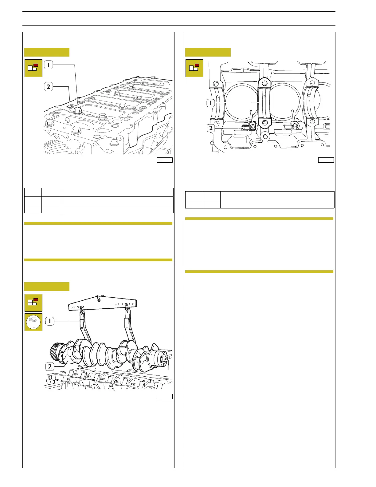
Main bearings and oil nipples removal
Figure 61
47571
Remove the main half-bearings (1).
Unscrew the screws and remove the oil sprayers (2).
Ref.
No. Description
(2) 6 M14x1.5screws
NOTE once the engine disassembly is complete, clean
accurately the removed parts and check their in-
tegrity.
The following pages give instructions for checks
andmainmeasurementstodoastodetermine
whether the parts can be reused.