SECTION 2 - OPERATING DIAGRAMS
17
CURSOR SERIES
Print P4D32C006 E Base - 03/2015
COOLING
227831
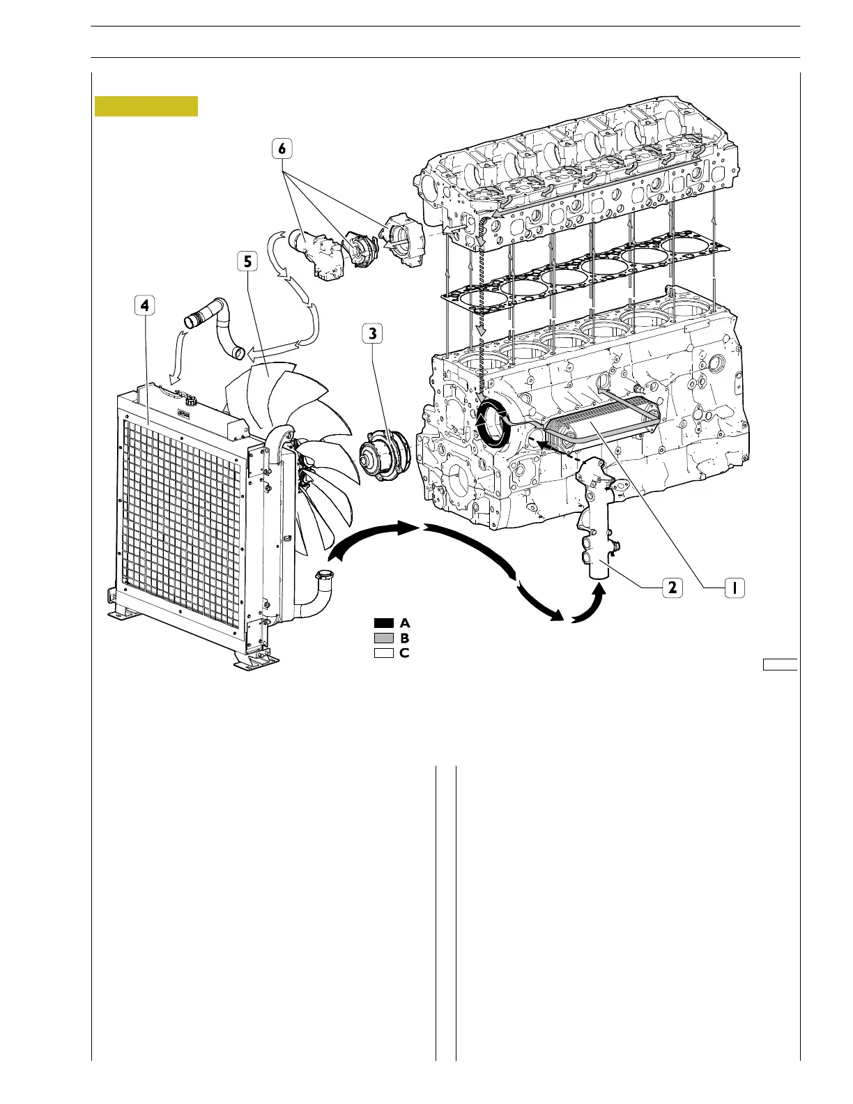
Figure 21
COOLING SYSTEM DIAGRAM
A. Water c oming into pump - B. Water circulating in the engine - C. Water leaving the thermostat
1. Water/oil heat exchanger - 2. Refitting water inlet pipe to pump - 3. Water pump - 4. Clean the heat exchanger with
aftercooler (radiator) - 5. Fan - 6. Thermostat case
Description
The engine cooling system is a closed circuit forced circula-
tion syst em and can be connected to an additional heater (if
any) and to the Intarder heat exchanger.
It con sists mainly of th e following components:
- an expansion tank and plug with two built-in valves: an
outlet and an inlet, which regulate the pressure of the
system;
- a coolant level sensor
- an engine cooling unit to dissipate the heat taken by the
coolant from with heat exchanger for aftercooler.
- a heat exchanger to cool the lubricant oil;
- a centrifugal water pump incorporated into the engine
crankcase;
- an electric fan;
- thermostat to control c oolant circulation.