SECTION 5 - REMOVAL - REFITTING OF THE MAIN ENGINE COMPONENTS
31
CURSOR SERIES
Print P4D32C006 E Base - 03/2015
Refitting
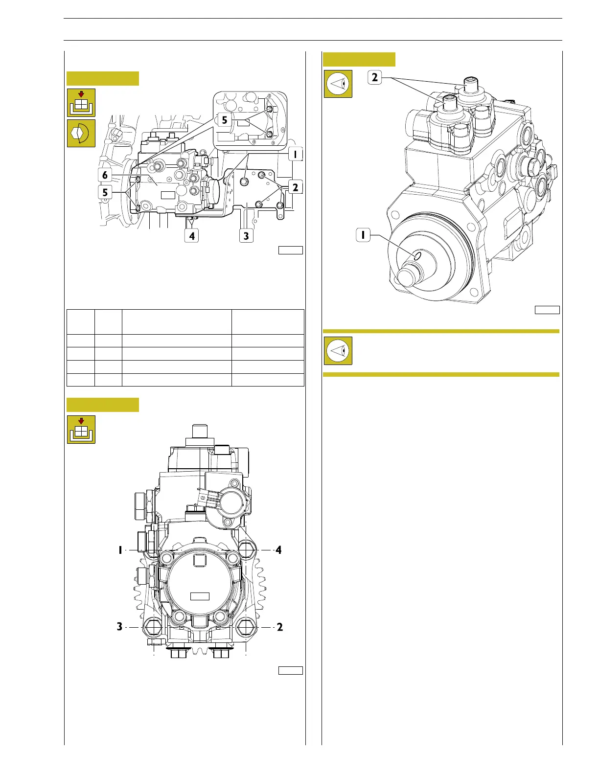
Figure 84
221104
Position the bracket (3) and tighten the screws (1, 2).
Position the high pressure pump (6) and tighten the screws (4,
5) to torque shown in the table.
Ref.
No. Description
Tightening
torques
(1) 2 Screws M10 X 1.5 X 20 37.5 ± 5 Nm
(2) 3 Screws M8 X 1.25 X 20 24.5 ± 2.5 Nm
(4) 2 Screw M12 X 1.75 X 30 32.5 ± 2.5 Nm
(5) 4 Screws M12 X 1.5 37.5 ± 2.5 Nm
Figure 85
225012
Observe the order of tightening indicated in the diagram.
Figure 86
187918
Fit the high pressure pump and make sure that the
seat of the key (1) on the pump shaft is facing the
pump intakes (2) .