SECTION 5 - REMOVAL - REFITTING OF THE MAIN ENGINE COMPONENTS
33
CURSOR SERIES
Print P4D32C006 E Base - 03/2015
Figure 89
221043
Fit the new blow-by filtering element (1) into its seat and
tighten the screws (2) to the torque indicated in the table.
Ref.
No. Description
Tightening
torques
(2) 3
ScrewsM6X1X40
Step 1 5Nm
Step 2 15 ± 1.5 Nm
NOTE Apply Loctite 243 to the screws (2).
Position the blow-by cover (4) and tighten the screws (3) to
thetorqueindicatedinthetable.
Ref.
No. Description
Tightening
torques
(3) 6 ScrewsM6X1X25 7±1Nm
Figure 90
221126
Tighten the fastening screws following the sequence indicated
in the figure.
Refit the air filter as described in the procedure “AIR FILTER
REMOVAL - REFITTING”.
TAPPET COVER
REMOVAL-REFITTING
Removal
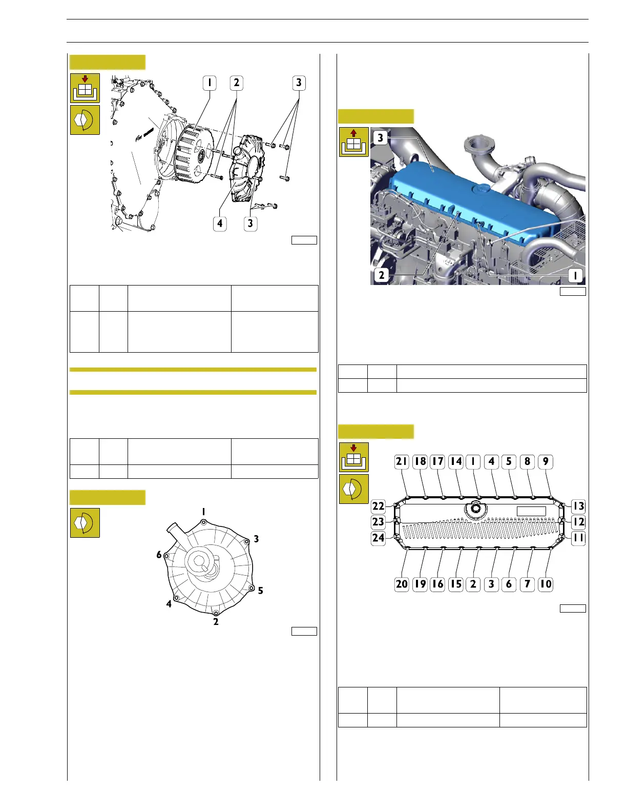
Figure 91
227771
Disconnect the electric connection of engine crankcase
pressure sensor (1).
Unscrew the fastening screws (2) and remove the tappet
cover (3) together with the gasket.
Ref.
No. Description
(2) 24 M6 x 1 screws
Refitting
Figure 92
221122
Position the cover and new gasket and insert all the screws.
Replace the screws in the sequence 1-10-20-21-9 and then in
the sequence shown in the figure until contact.
Tighten the screws (1-24 ) to the torque specified in the table.
Ref.
No. Description
Tightening
torques
(-) 24 M6 x 1 screws 8.5 ± 1.5 Nm
Connect the electric connection of engine crankcase pressure
sensor (1).