SECTION 6 - GENERAL MECHANICAL OVERHAUL
85
CURSOR SERIES
Print P4D32C006 E Base - 03/2015
Figure 204
221121
Fit the gear (2) and tighten the nut (1) to the torque shown
in the table.
Remove tool 99360612.
Ref.
No. Description
Tightening
torques
(1) 1 Nut M24x1.5 275 ± 25 Nm
Intake and exhaust rocker arm clearance
adjustment
NOTE The adjustment of clearance between the roc-
ker arms and crosspieces controlling the intake
and exhaust valves must be done very carefully.
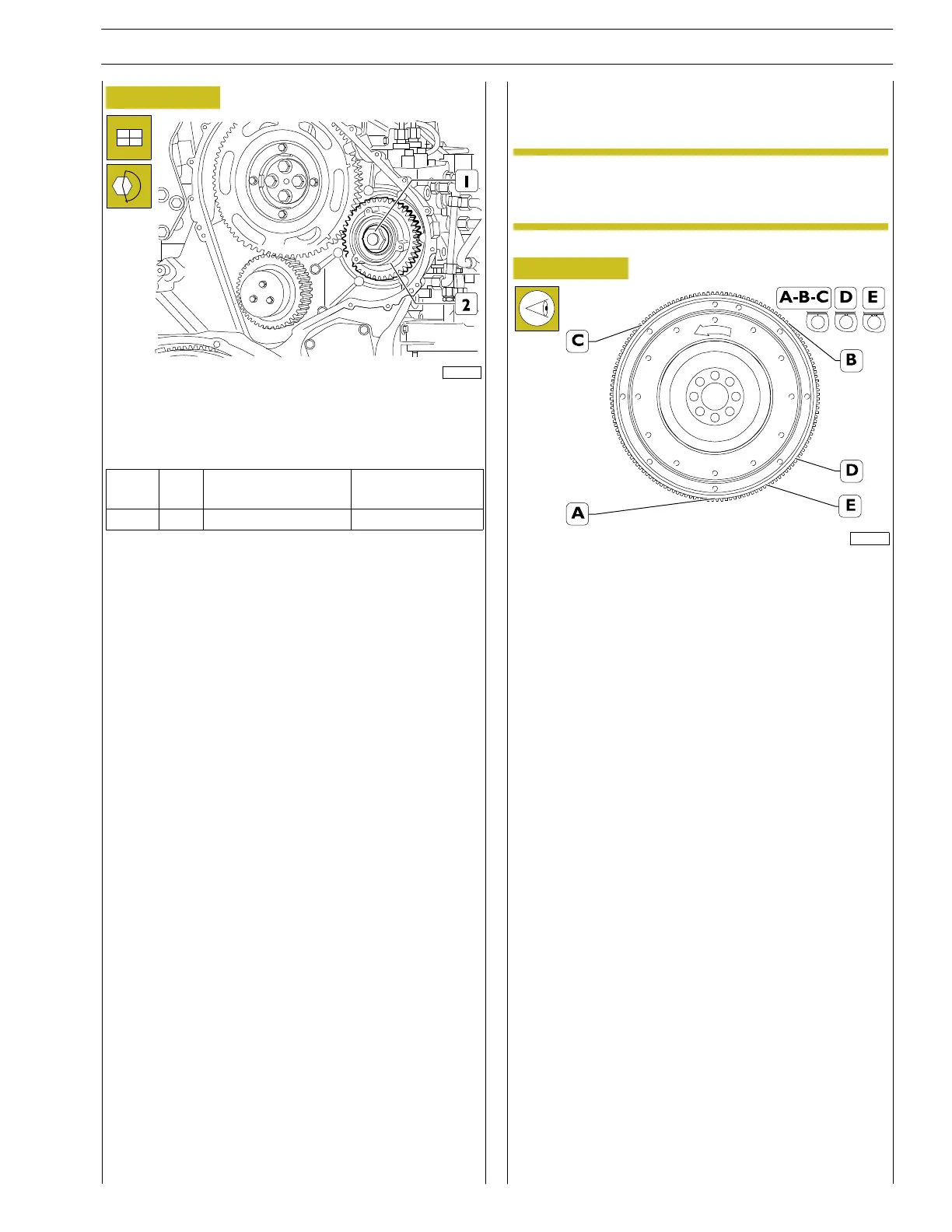
Figure 205
221128
A Hole on flywheel with reference mark, corresponding to
the TDC of pistons 1-6
B Hole on flywheel with reference mark, corresponding to
the TDC of pistons 2-5
C Hole on flywheel with reference mark, corresponding to
the TDC of pistons 3-4
D Flywheel hole with two notches corresponding to posi-
tion 54˚ before TDC of pistons 1-6 (camshaft timing refe-
rence );
E Flywheel hole with three notches corresponding to posi-
tion 30˚ before TDC of pistons 1-6 (reference to high
pressure fuel pump timing system and phonic wheel
timing).
In order to perform adjustments correctly, during each rota-
tion phase, check the positioning accuracy using the tool for
TDC Engine 99360612, inserting it into the hole marked with
a notch on the flywheel corresponding to the position of the
pistons.