10
SECTION 6 - GENERAL MECHANICAL OVERHAUL
CURSOR SERIES
Base - 03/2015 Print P4D32C006 E
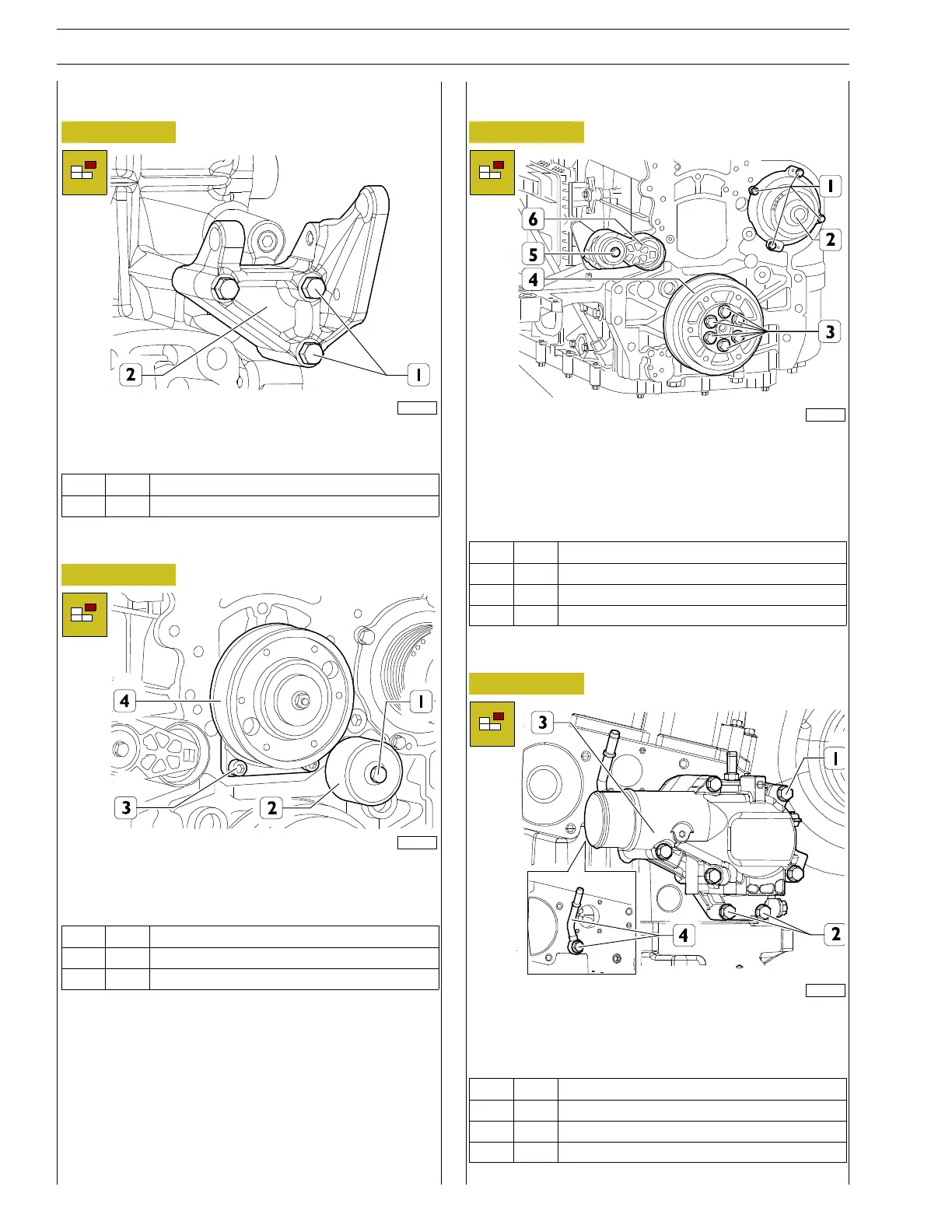
Alternator support removal
Figure 15
224063
Unscrew the screws (1) and remove the alternator support
(2).
Ref.
No. Description
(1) 3 M10x1.5screws
Electromagnetic coupling pulley removal
Figure 16
225023
Unscrew the screws (1) and remove the fixed belt tensioner
(2), undo the screws (3) and remove the electromagnetic cou-
pling pulley assembly (4).
Ref.
No. Description
(1) 1 M12 x 1.75 screw
(3) 5 Screws M12 X 1.75
Assembly of auxiliary parts
Figure 17
225016
Unscrew the screw (5) and remove the automatic belt ten-
sioner (6).
Unscrew the screws (3) and remove the crankshaft pulley (4).
Unscrew the screws (1) and remove the water pump (2) and
its gasket.
Ref.
No. Description
(1) 3 Screws M18 X 1.25 X 20
(3) 6 M14 x 2 screws
(5) 1 M10x1.5screw
Thermostat case removal
Figure 18
224067
Unscrew the screws (1, 2) and remove the thermostat cover
and relative gaskets.
Unscrew the fixing screws and remove the degasing pipe (4).
Ref.
No. Description
(1) 5 Screws M8 X 1.25 X 100
(2) 2 Screws M8 X 1.25 X 50
(4) 1 Fitting M10 X1.5