30
SECTION 5 - R EMOVAL - REFITTING OF THE MAIN ENGINE COMPONENTS
CURSOR SERIES
Base - 03/2015 Print P4D32C006 E
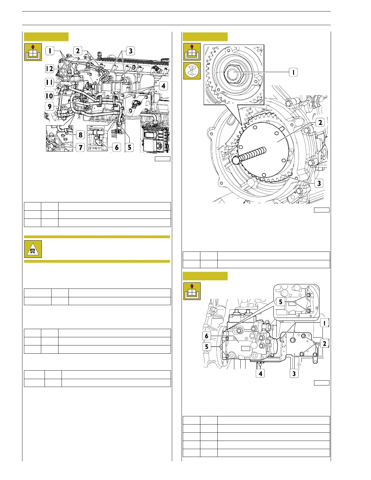
Figure 81
227770
Disconnect the electrical connection from the fuel flow
regulator.
Unscrew the nutes (2), remove the plugs, undo the fittings (1,
3) and remove the HP fuel pipes.
Ref.
No. Description
(1, 3) 4 Fittings M16 X 1.5
(2) 2 Nuts M6 X 1
The HP pipes that are disassembled cannot be used
again and must be replaced.
Open springs (4), remove the fittings (5, 9, 12) and remove the
LP fuel pipes from pump to filter and vice-versa.
Ref.
No. Description
(5,9,12) 4 Fittings M18 X 1.5
Undo the fitting (10), bracket retainer screws (6, 8) and move
the LP fuel pipe from control unit to pump off to the side.
Ref.
No. Description
(6, 8) 2 Screws M8 X 1.25 X 16
(10) 1 Fitting M22 X 1.5
Unscrew the fittings (7, 11) and remove the fuel return pipe.
Ref.
No. Description
(7, 11) 2 Fittings M18 X 1.5
Figure 82
225036
Undo the nut (1).
Apply the tool to extract the high pressure pump gear
99366198 (2) and remove the high pressure pump control
gear (3).
Ref.
No. Description
(1) 1 Nut M24 X 1.5
Figure 83
221104
Unscrew the screws (1,2,4) and remove the bracket (3).
Unscrew the screws (5) and remove the high pressure pump
(6).
Ref.
No. Description
(1) 2 ScrewsM10X1.5X20
(2) 2 Screws M8 X 1.25 X 20
(4) 2 Screws M12 X 1.75 X 30
(5) 4 Screws M12 X 1.5