56
SECTION 6 - GENERAL MECHANICAL OVERHAUL
CURSOR SERIES
Base - 03/2015 Print P4D32C006 E
Figure 128
47506
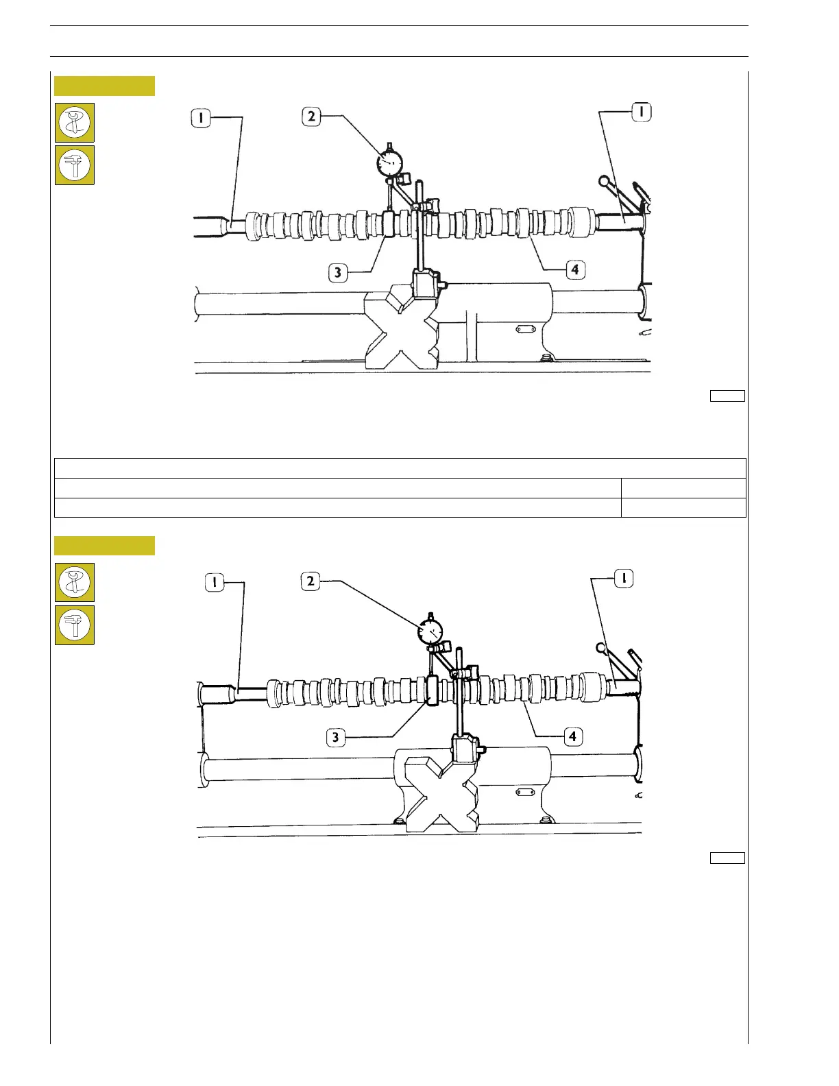
Place the camshaft (4) on the tailstocks (1) and check the lift of the cams (3) using a dial gauge (2), comparing the values with those
specified below.
Technical data
Intake valve control cam lift 9.231 mm
Exhaust valve control cam lift 9.5607 mm
Figure 129
47507
Still with the camshaft (4) set on tailstocks (1), check the alignment of the supporting pins (3) with the dial gauge (2); it must not
exceed 0.030 mm.
If the disalignment exceeds this value, replace the shaft: