1. Packets arrive at an incoming PIC interface.
2. The PIC passes the packets through the midplane to the FEB, where the I/O Manager
ASIC breaks them into 64-byte cells.
3. The Distributed Buffer Manager ASIC on the FEB distributes the data cells throughout
memory banks on the FEB.
4. The Internet Processor II ASIC on the FEB performs route lookups and makes
forwarding decisions.
5. The Internet Processor II ASIC notifies a second Distributed Buffer Manager ASIC on
the FEB, which forwards the notification to the outgoing interface.
6. The I/O Manager ASIC on the FEB reassembles data cells in shared memory into data
packets as they are ready for transmission and passes them to the outgoing PIC
through the midplane.
7. The outgoing PIC transmits the data packets.
Related
Documentation
M5 and M10 Internet Router Overview on page 4•
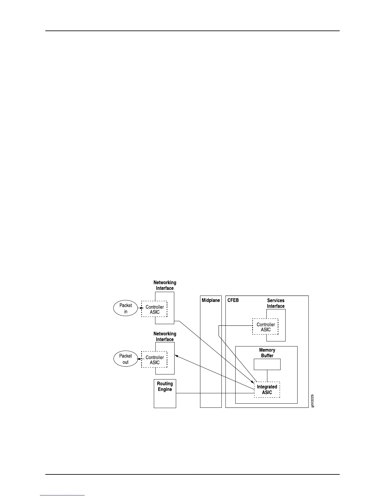
Data Flow Through the M7i Router Packet Forwarding Engine
Data flows through the M7i router Packet Forwarding Engine in the following sequence
shown in Figure 24 on page 123. Use of ASICs promotes efficient movement of data packets
through the system.
Figure 24: M7i Router Packet Forwarding Engine Components and Data
Flow
1. Packets arrive at an incoming networking interface.
2. The networking interface passes the packets to the CFEB, where the integrated ASIC
processes the packet headers, divides the packets into 64-byte data cells, and
distributes the data cells throughout the memory buffer.
123Copyright © 2012, Juniper Networks, Inc.
Chapter 4: Monitoring Key Router Components