•
Monitoring and control of router components—The HCM collects statistics from all
sensors in the system. When it detects a failure or alarm condition, it sends a signal to
the Routing Engine, which generates control messages or sets an alarm. The HCM also
relays control messages from the Routing Engine to the router components.
•
Controlling component power-up and power-down—The HCM controls the power-up
sequence of router components as they start and powers down components when
their offline buttons are pressed.
•
Signaling of mastership—In a router with more than one Routing Engine, the HCM
signals to all router components which Routing Engine is the master and which is the
standby.
•
Alarm display—The HCM provides status and troubleshooting information at a glance.
It is located on the front of the chassis below the FPC card cage, as shown in Figure
272 on page 534. The LEDs on the HCM include two alarm LEDs. The circular red alarm
LED at the upper right of the craft interface indicates a critical condition that can result
in a system shutdown. The triangular yellow alarm below it indicates a less severe
condition that requires monitoring or maintenance. Both alarms can occur
simultaneously.
•
PIC removal—If a PIC offline button is pressed, the HCM relays the request to the
Compact Forwarding Engine Board (CFEB), which takes the PIC offline and informs
the Routing Engine. Other PICs are unaffected, and system operation continues.
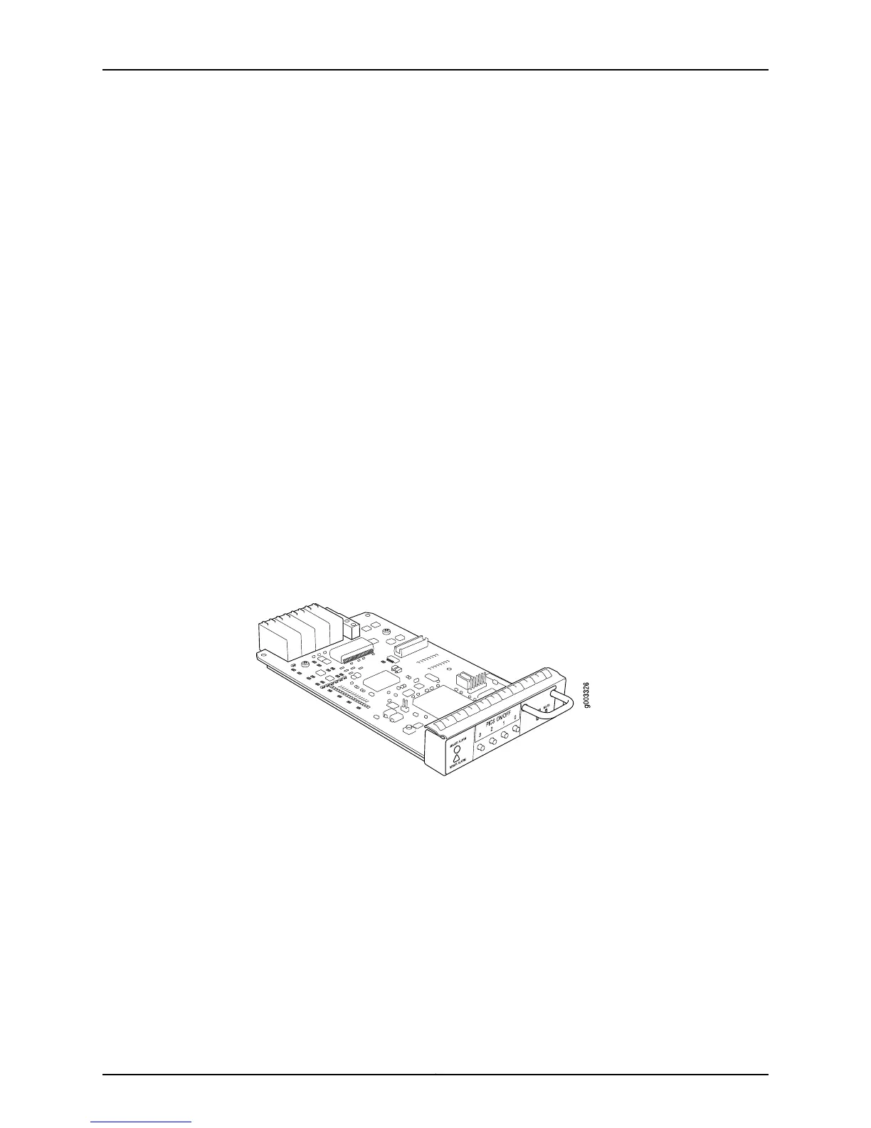
Figure 271 on page 533 shows the M10i router HCM component.
Figure 271: M10i Router HCM Component
The HCM has the following components:
•
100-Mbps Fast Ethernet switch—Carries signals and monitoring data between router
components.
•
Two LEDs—Indicate HCM status. The green LED is labeled PWR and the blue LED
labeled MSTR. See “Check HCM LEDs” on page 534.
•
Alarm LEDs—Display alarm conditions, if any exist.
•
PIC offline buttons—Relay a request to the CFEB, which prepares a PIC for removal
from the router, or brings the PIC online when it is replaced.
Two HCMs are installed into the midplane from the front of the chassis, as shown in
Figure 272 on page 534. The master HCM performs all functions and provides PIC removal
533Copyright © 2012, Juniper Networks, Inc.
Chapter 25: Monitoring the HCM