M120 Router Cable Management System
The cable management system (see Figure 186 on page 356) consists of a row of nine
semicircular plastic bobbins mounted on the front of the router below the FPC card cage.
The PIC cables pass between the bobbins and into the tray, keeping the cables organized
and securely in place. The curvature of the bobbins also helps maintain the proper bend
radius for optical PIC cables.
You can pull the cable management system up and outward to lock it into the
maintenance position. This allows you to access the lower fan tray and the front air filter.
Figure 186: M120 Router Cable Management System
Related
Documentation
Checklist for Maintaining Cables and Connectors on page 351•
M320 Router Cable Management System
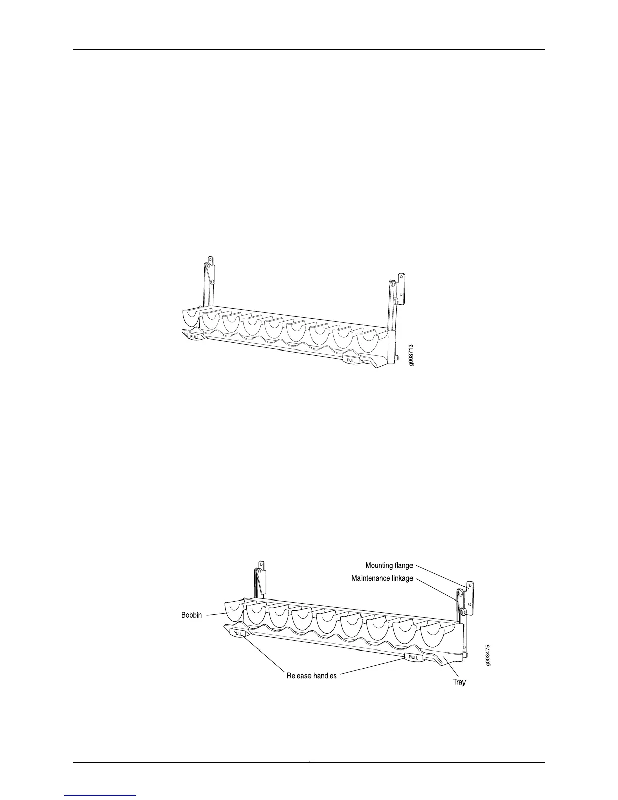
The M320 router cable management system consists of a row of nine semicircular plastic
bobbins mounted on the front of the router below the FPC card cage (see Figure 187 on
page 356). The PIC cables pass between the bobbins and into the tray, keeping the cables
organized and securely in place. The curvature of the bobbins also helps maintain the
proper bend radius for optical PIC cables.
You can pull the cable management system up and outward to lock it into the
maintenance position. This allows you to access the lower fan tray and the front air filter.
Figure 187: M320 Router Cable Management System
Related
Documentation
Checklist for Maintaining Cables and Connectors on page 351•
Copyright © 2012, Juniper Networks, Inc.356
M Series and T Series Routers Monitoring and Troubleshooting Guide