Related
Documentation
Checklist for Monitoring Redundant Cooling System Components on page 623•
M20 Router Redundant Cooling System Components
The M20 router cooling system includes:
•
Three front fan trays—Cool the Flexible PIC Concentrators (FPCs) and the System and
Switch Board (SSB). These fan trays are located on the left front side of the chassis.
•
One rear fan tray—Cools the Routing Engine. This fan tray is located immediately to
the right of the Routing Engine.
•
Power supply integrated fan—A built-in fan cools each power supply.
The four fan trays plug directly into the router midplane and work together to provide
side-by-side cooling.
The fans operate in unison to maintain an acceptable operating temperature for the
Routing Engine and midplane. Each cooling subsystem maintains a separate airflow, and
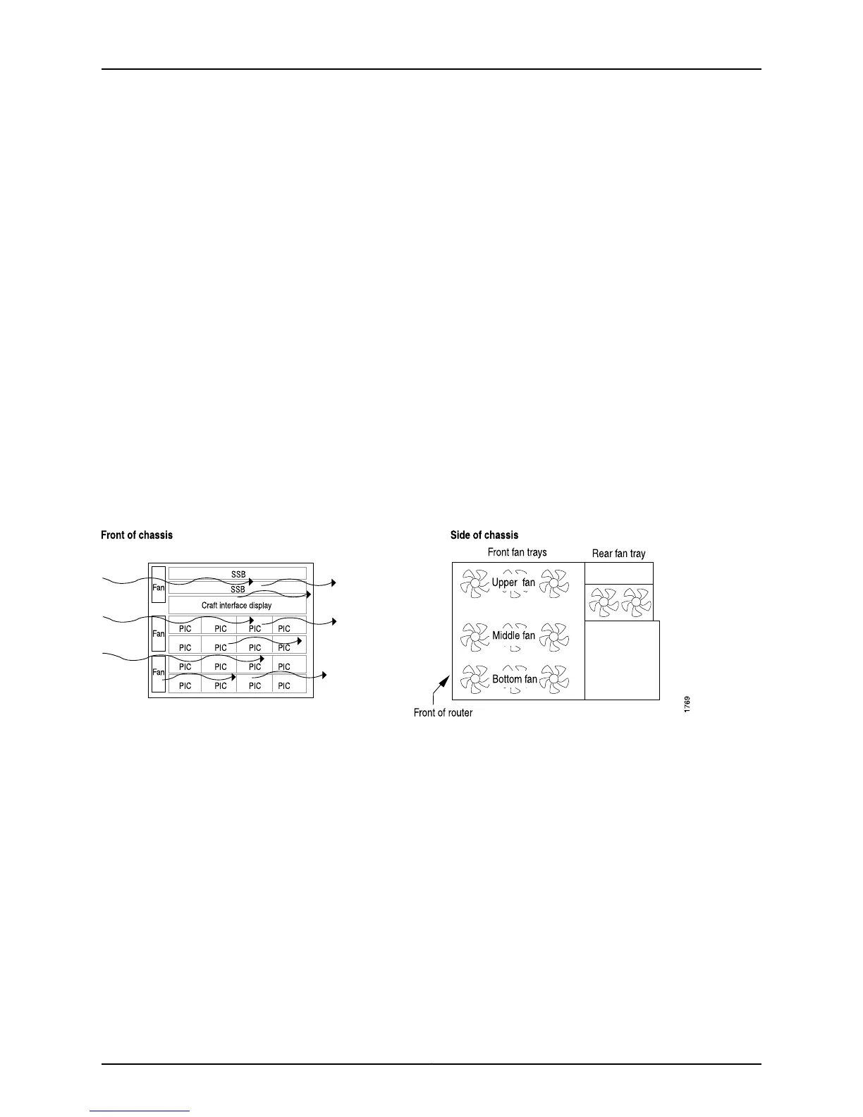
each is monitored independently for temperature control.Figure 312 on page 628 shows
the M20 router cooling system components and airflow.
Figure 312: M20 Router Cooling System and Airflow
Both front and rear fan trays are hot-removable and hot-insertable. You can remove and
replace these components without powering down the system and disrupting routing
functions. Figure 313 on page 629 shows the M20 router cooling system components.
Copyright © 2012, Juniper Networks, Inc.628
M Series and T Series Routers Monitoring and Troubleshooting Guide