should happen. For example, you can use the set interface-control failover
other-routing-engine statement at the [edit system processes] hierarchy level to configure
failover for the interface control daemon.
Related
Documentation
Checklist for Host Redundancy on page 563•
Redundancy Connection for an M10i Router
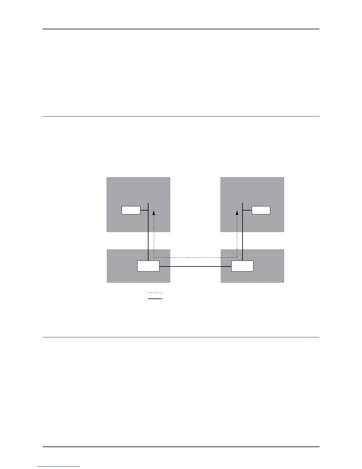
Figure 287 on page 571 shows the connection between the master and backup Routing
Engines on an M10i router. Keepalive messages are sent between Routing Engines via
the interconnected HCM switches. In this way, the master and the backup Routing Engines
exchange state information.
Figure 287: Redundancy Connection for an M10i Router
Master Routing Engine
RE0
HCM0 HCM1
RE1
Backup Routing Engine
SwitchSwitch
keepalive messages
physical connection
g004450
FXP1 FXP1
Related
Documentation
M10i Router Redundant Routing Engines and HCMs on page 566•
Redundancy Connection for an M20 Router
Figure 288 on page 572 shows the connection between the master and backup Routing
Engines on an M20 router. Keepalive messages are sent between the master and backup
Routing Engine through the switch on the SSB. In this way, the master and the backup
Routing Engines exchange state information.
571Copyright © 2012, Juniper Networks, Inc.
Chapter 28: Host Redundancy Overview