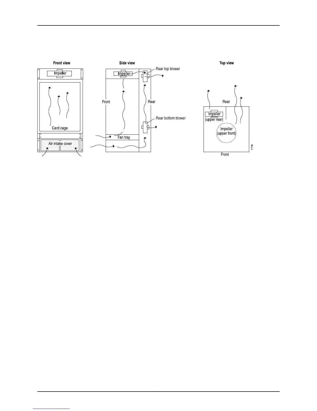
Figure 163: M40e and M160 Router Cooling System and Airflow
Related
Documentation
Checklist for Monitoring the Cooling System on page 317•
M120 Router Cooling System
The cooling system consists of the following components:
•
Two front fan trays
•
Two rear fan trays
•
Front air filter
The cooling system components work together to keep all router components within the
acceptable temperature range (see Figure 164 on page 328, Figure 165 on page 328, and
Figure 166 on page 328). The router cooling system comprises two front and two rear fan
trays (see Front View of a Fully Configured Router Chassis and Rear View of a Fully
Configured AC-Powered Router Chassis). Both the front and rear fan trays install
horizontally above and below the front and rear card cages. Each fan tray contains eight
fans. The two front fan trays are interchangeable, the two rear fan trays are
interchangeable, but the front and rear fan trays are not interchangeable. The fan trays
are hot-insertable and hot-removable. The front fan trays cool the components installed
in the front card cage (the FPCs, CFPCs, PICs, and craft interface). The rear fan trays cool
the components installed in the rear card cage (the Routing Engines, CBs, power supplies,
and FEBs). Figure 164 on page 328 shows the airflow through the router.
An air filter in the front in the chassis located beneath the lower fan tray helps keep dust
and other particles from entering the cooling system. To function properly, the entire
cooling system requires an unobstructed airflow and proper clearance around the site,
as described in M120 Clearance Requirements for Airflow and Hardware Maintenance.
327Copyright © 2012, Juniper Networks, Inc.
Chapter 11: Monitoring the Cooling System