•
CONSOLE—Connects the Routing Engine to a system console through an RS-232
(EIA-232) serial cable.
•
AUXILIARY— Connects the Routing Engine to a laptop, modem, or other auxiliary device
through an RS-232 (EIA-232) serial cable.
At the center of the CIP are two ports labeled BITS A and BITS B. These are the BITS
connectors to the MCS. The router does not support BITS input, so these ports currently
do not function.
The CIP has two sets of alarm relay contacts for connecting the router to external alarm
devices. Whenever a system condition triggers either the red or yellow alarm on the craft
interface, the alarm relay contacts are also activated. The alarm relay contacts are
located below the BITS interface ports.
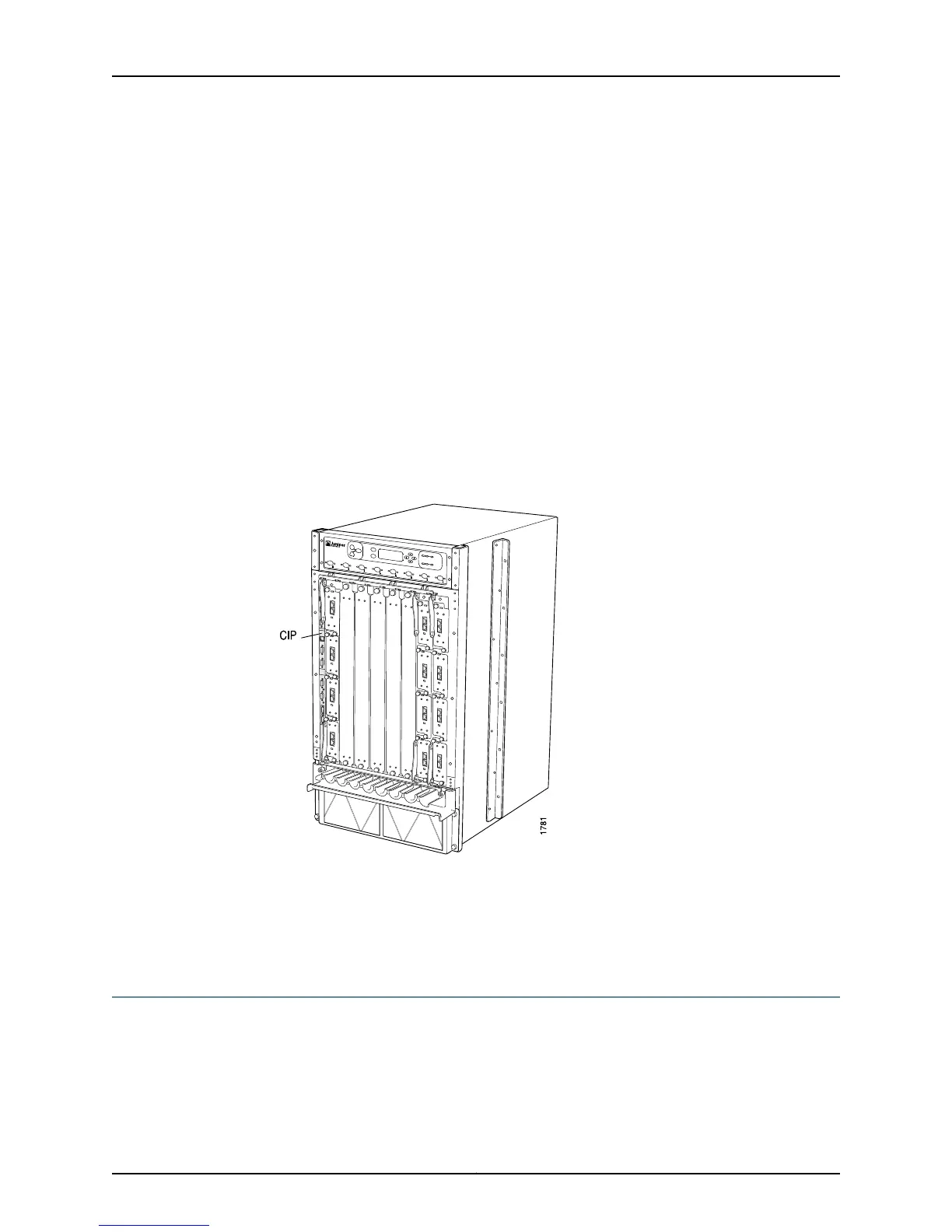
The CIP is located on the left side of the M40e and M160 router Flexible PIC Concentrator
(FPC) card cage (see Figure 256 on page 482).
Figure 256: M40e and M160 Router CIP Location
The CIP is field-replaceable, but is not hot-removable, hot-insertable, or hot-pluggable.
You must power down the router before removing or installing it.
Related
Documentation
Checklist for Monitoring the CIP on page 479•
Monitor the CIP Status
Purpose To monitor the CIP status.
Action To monitor the CIP status, use the following command:
user@host> show chassis environment
Copyright © 2012, Juniper Networks, Inc.482
M Series and T Series Routers Monitoring and Troubleshooting Guide