TX Matrix Router and TX Matrix Plus Router Routing Engine Redundancy
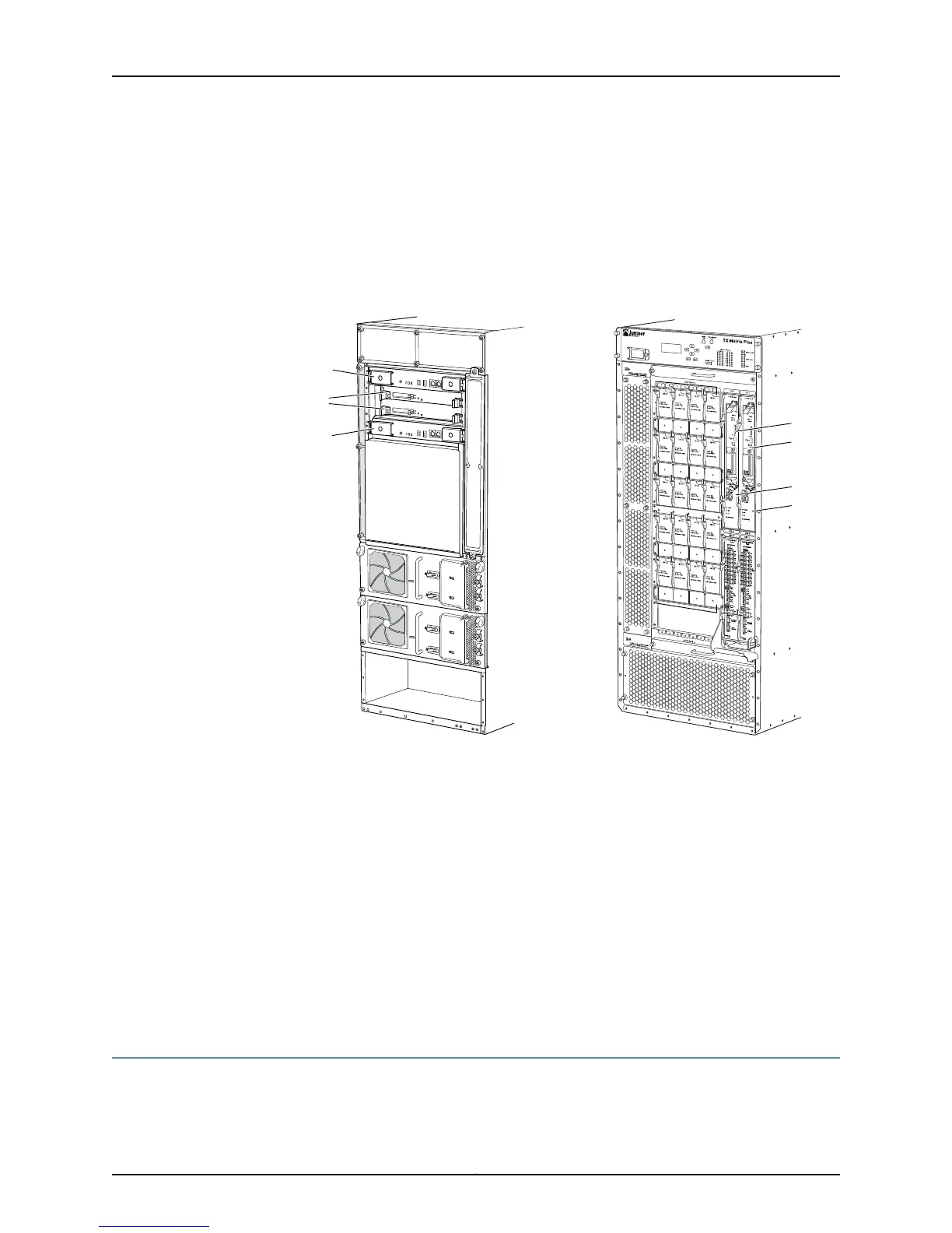
Figure 298 on page 598 shows the TX Matrix router and TX Matrix Plus router redundant
Routing Engines that are components of the host subsystem.
Figure 298: TX Matrix Router and TX Matrix Plus Router Routing Engines
g006596
TX-CB-1
TX-CB-0
TX Matrix
TX Matrix Plus
Routing
Engines
CB 0
CB 1
RE 0
RE 1
Both the Routing Engine and the Control Board must be installed for the host subsystem
to function. When two host subsystems are installed in the router, both are powered on,
but only one is the master; the second host subsystem is the backup and performs no
functions. By default, the master host subsystem has components installed in slots RE0
and CB0; the backup host module has components installed in slots RE1 and CB1. If one
Routing Engine physically fails, the other one assumes the routing functions. If a software
failure occurs, the other backup Routing Engine assumes routing functions if some
preliminary configuration has been done.
The routing engine LEDs indicate the Routing Engine operating status and mastership.
Related
Documentation
Check the TX Matrix Router Routing Engine LEDs on page 189•
• Check the TX Matrix Plus Router Routing Engine LEDs on page 190
Redundant Routing Engine Automatic Failover Overview
If the keepalive time is configured for 2 seconds, the sequence of events is as follows:
Copyright © 2012, Juniper Networks, Inc.598
M Series and T Series Routers Monitoring and Troubleshooting Guide