Check the PCG LED Status on the Faceplate
Purpose To check the LED status of the PCG on the faceplate.
Action To check the PCG LEDs, remove the rear component cover and look on the PCG faceplate
at the rear of the M40e or M160 router chassis.
Table 156 on page 708 describes the functions of these LEDs.
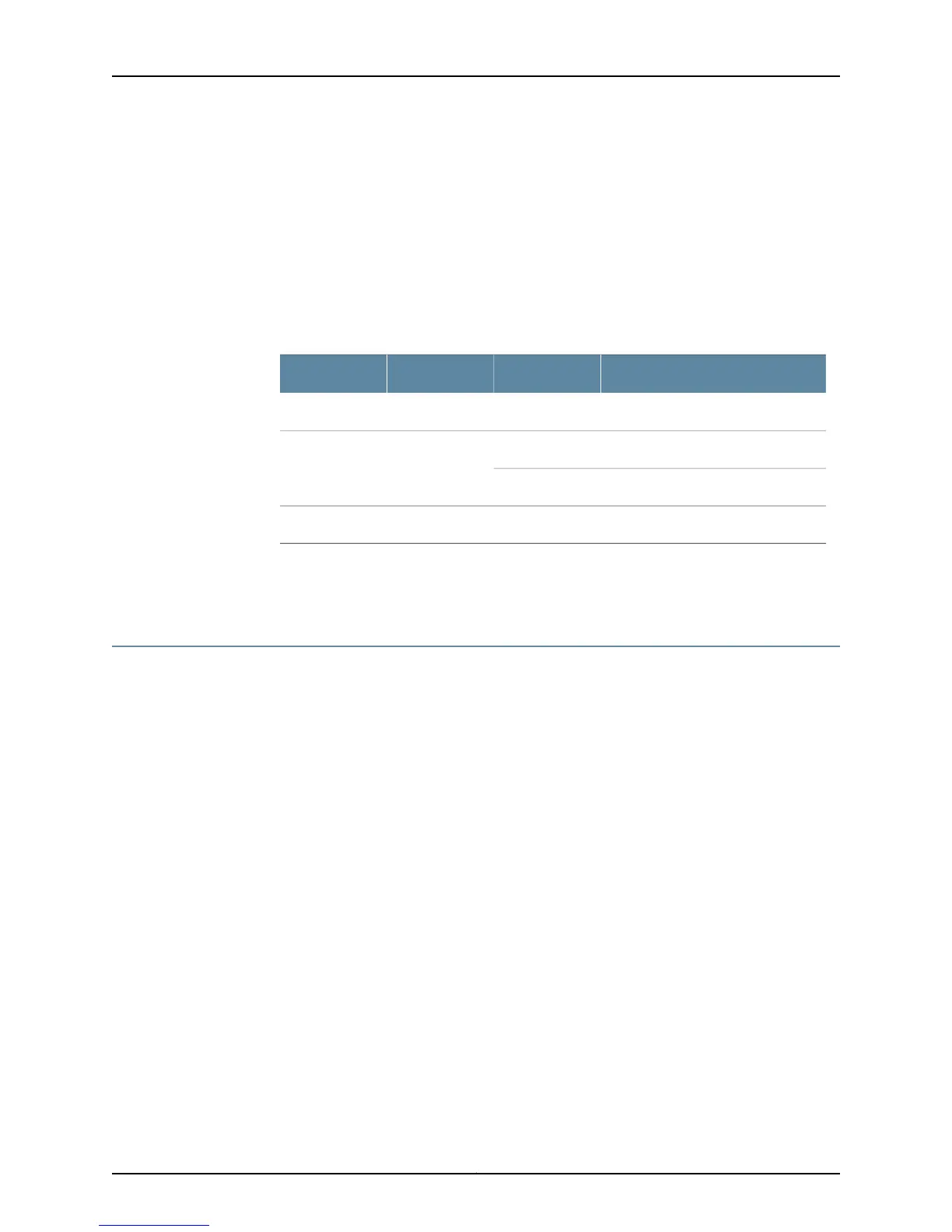
Table 156: PCG LEDs
DescriptionStateLabelColor
PCG is master.On steadilyMASTERBlue
PCG is operating normally.On steadilyOKGreen
PCG is starting up.Blinking
PCG has failed.On steadilyFAILAmber
Related
Documentation
Checklist for Monitoring Redundant PCGs on page 703•
Determine Redundant PCG Mastership
If both PCGs are installed and functioning normally, PCG0 is the master and PCG1 is the
backup by default.
To determine which PCG is operating as the master:
1.
Display the PCG Master from the Craft Interface on page 708
2.
Check the PCG LEDs for Mastership on the Faceplate on page 709
3.
Display the Packet Forwarding Engine Current Clock Source on page 709
Display the PCG Master from the Craft Interface
Purpose To obtain status information about the PCG mastership from the craft interface.
Action To determine the PCG master from the craft interface status information, use the following
command:
user@host> show chassis craft-interface
Sample Output
user@host> show chassis craft-interface
[...Output truncated...]
PCG LEDs:
PCG 0 1
--------------
Copyright © 2012, Juniper Networks, Inc.708
M Series and T Series Routers Monitoring and Troubleshooting Guide