buttons for the first FPC. The standby HCM provides PIC removal buttons for the second
FPC. The HCM in the slot labeled HCM0 is paired with the Routing Engine in the slot
labeled RE0. Likewise, the HCM in the slot labeled HCM1 is paired with the Routing Engine
in the slot labeled RE1. By default, the HCM in the slot labeled HCM0 is the master.
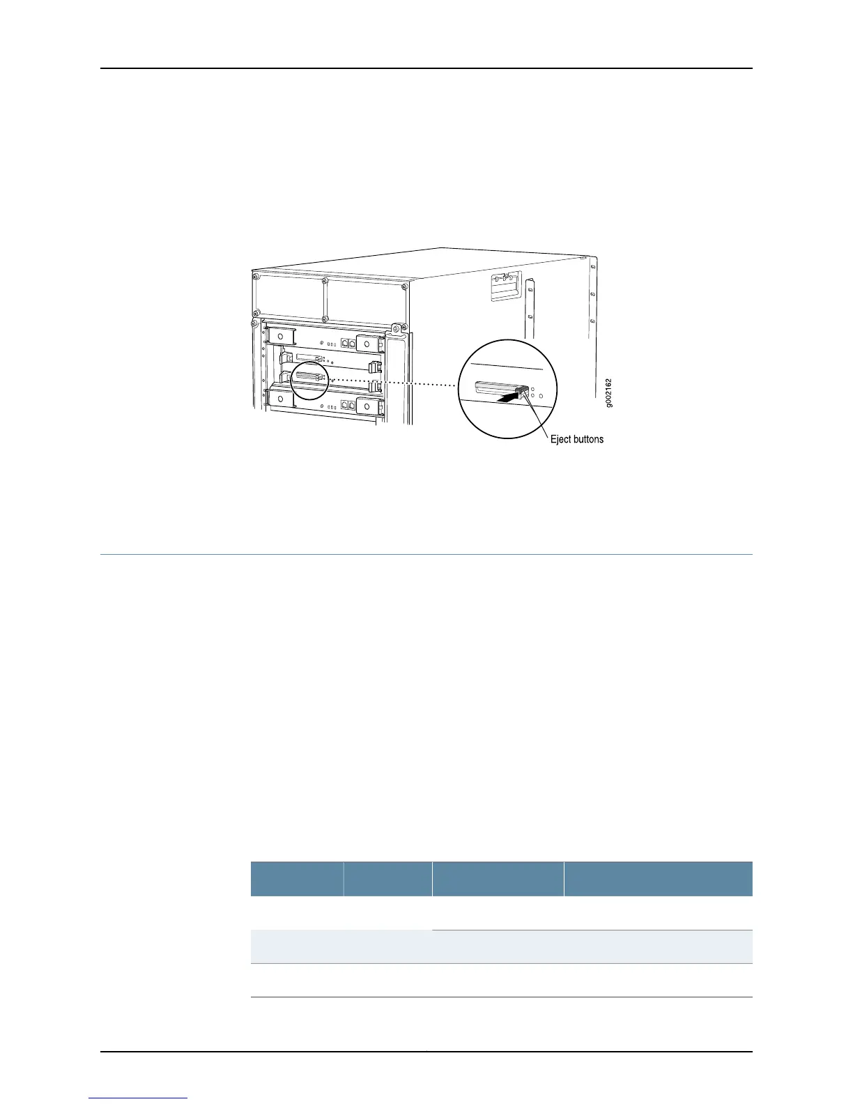
Figure 272: M10i Router HCM Location
The HCM is hot-pluggable.
To return the HCM, see “Return the Failed Component” on page 116 or follow the
instructions in the M10i Multiservice Edge Router Hardware Guide.
Monitor the HCM Status
To monitor the HCM status:
1.
Check HCM LEDs on page 534
2.
Check HCM Environmental Status on page 535
3.
Check the Companion Routing Engine Status on page 535
Check HCM LEDs
Purpose To monitor the HCM status by checking the HCM LEDs on the component faceplate.
Action To check the HCM LEDs, look at the component faceplate at the bottom left front of the
M10i router chassis (see Table 130 on page 534).
Two LEDs indicate HCM status—a green PWR LED and a blue MSTR LED. describes the
LED states.
Table 130: HCM LEDs
DescriptionStateColorLabel
HCM is functioning normallyOn steadilyGreenPWR
HCM is starting up.Blinking
HCM is master.On steadilyBlueMSTR
Copyright © 2012, Juniper Networks, Inc.534
M Series and T Series Routers Monitoring and Troubleshooting Guide