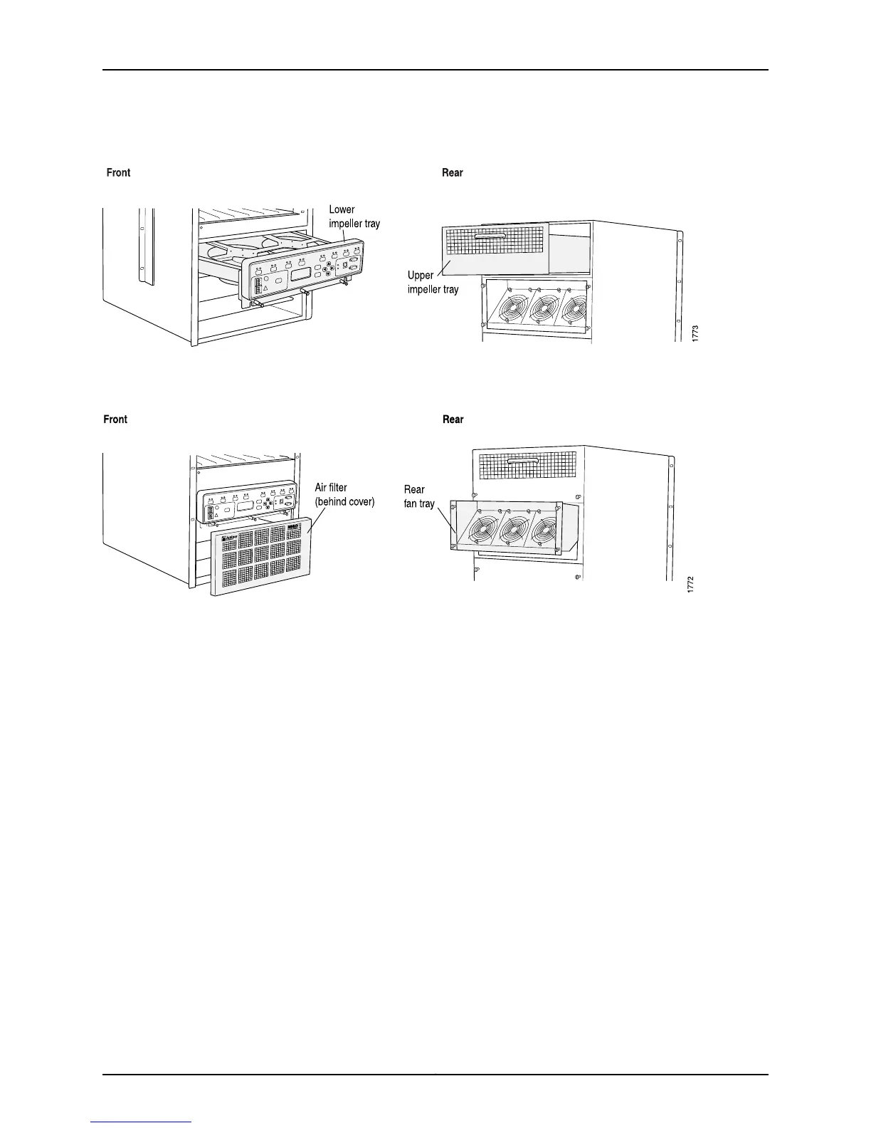
Figure 314: M40 Router Impeller Trays
Figure 315 on page 630 shows the M40 router air filter and fan tray.
Figure 315: M40 Router Air Filter and Fan Tray
Related
Documentation
Checklist for Monitoring Redundant Cooling System Components on page 623•
M40e and M160 Router Redundant Cooling System Components
The M40e and M160 routers include the following cooling system components:
•
Front cooling subsystem—Cools the FPCs, PICs, and midplane. It includes a fan tray
located behind the cable management system and a large, central impeller behind
the craft interface (fan tray front left, fan tray front right, fan tray rear left, fan tray rear
right, and front top blower).
•
Rear cooling subsystem—Cools the Switching and Forwarding Modules (SFMs), host
module, PFE Clock Generators (PCGs), and power supplies. It includes one impeller
located at the upper right of the chassis rear and another at the lower left (rear top
blower and rear bottom blower). The upper and lower impellers are not
interchangeable.
Figure 316 on page 631 shows the M40e and M160 router cooling system components
and airflow.
Copyright © 2012, Juniper Networks, Inc.630
M Series and T Series Routers Monitoring and Troubleshooting Guide