Figure 313: M20 Router Cooling System Components
g001770
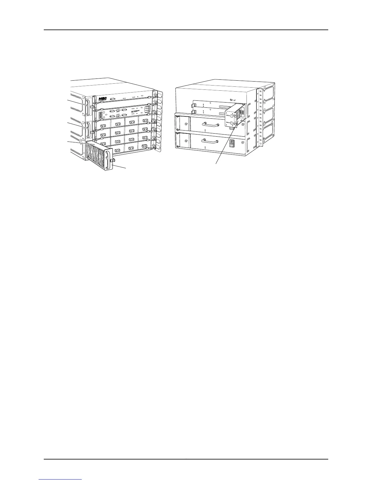
Front fan tray(s) Rear fan tray
Upper fan
Middle fan
Bottom fan
RearFront
Related
Documentation
Checklist for Monitoring Redundant Cooling System Components on page 623•
M40 Router Redundant Cooling System Components
The M40 router cooling system consists of three separate subsystems (see Figure 314
on page 630):
•
Impellers—Two redundant pairs of impellers (top impeller and bottom impeller) cool
the Packet Forwarding Engine components (backplane, System Control Board [SCB],
FPCs, and PICs). During normal operation, both pairs of impellers function at less than
full capacity.
•
Triple fan assemblies—Three load-sharing fans cool the backplane and the Routing
Engine (rear left fan, rear center fan, and rear right fan).
•
Power supply integrated fan—A built-in fan cools each power supply.
Each cooling subsystem maintains a separate airflow, and each is monitored
independently for temperature control.
Temperature sensors on the backplane, the SCB, and the FPCs control the speed of the
impellers. Impeller failure triggers the red alarm LED on the craft interface. If the
temperature passes a certain threshold, the Junos OS turns off the power supplies.
The M40 router is designed to run normally with all three fans sharing the load equally
and running at half speed.
Figure 314 on page 630 shows the M40 router cooling system impeller trays.
629Copyright © 2012, Juniper Networks, Inc.
Chapter 31: Monitoring Redundant Cooling System Components