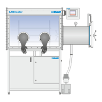
4 Transport, installation and commissioning
Installation
MB-20-G/MB-200G-W_MB-LABmaster_MB-200 MOD_TP700
Operating Manual - V5.0 - 04/2018 - STD
Page
4 - 15
Inlet Outlet
Pressure at sup-
ply point
Flange at connec-
tion point
Pressure at con-
nection point
Flange at connec-
tion point
1a Working gas INLET 1b Vacuum pump EXHAUST
5.5 – 6.0 bar
(0.55 – 0.60
MPa)
∅ 10 mm
Depressurized DN 25
2b Working gas purge outlet with op-
tional features
¡ glovebox purge (MB-BS-200)
¡ ECO Mode (MB-ECO Mode)
Depressurized Ø 42.5 mm
3a Regeneration gas INLET (for
RKM )
3b Regeneration gas EXHAUST (for
RKM and MB-LMF 2/40 REG )
0.3 … 0.5 bar
(30 … 40 kPa)
Ø 10 mm Depressurised Ø 10 mm
4a Cooling water INLET 4b Cooling water OUTLET
2.0 bar (0.2
MPa) … max.
2.5 bar (0.25
MPa)
10°C … 15°C
Ø 10 mm Low pressure Ø 10 mm
5a Box Purge
11
INLET 5b Box Purge* OUTLET
2.0 bar
(0.2 MPa)
Ø 10 mm Low pressure KF40, Ø
44.5mm
6b Option: Pressure relief valve OUT-
LET (OSV valves)
Low pressure KF40, Ø
44.5mm
The table above shows an overview about the inlets and outlets. The following sections
give further information. The numbers used in the titles correspond to the numbers in the
table.
11
Glovebox is purged directly from an external working gas source (gas purifier is bypassed):
¡ during manual inertisation through an open flange and a hose,
¡ as an optional (Siemens PLC-controlled feature) for glovebox operation.