214 Chapter 11: Graphic Equaliser (GEQ)
XL8 Control Centre
Operator Manual
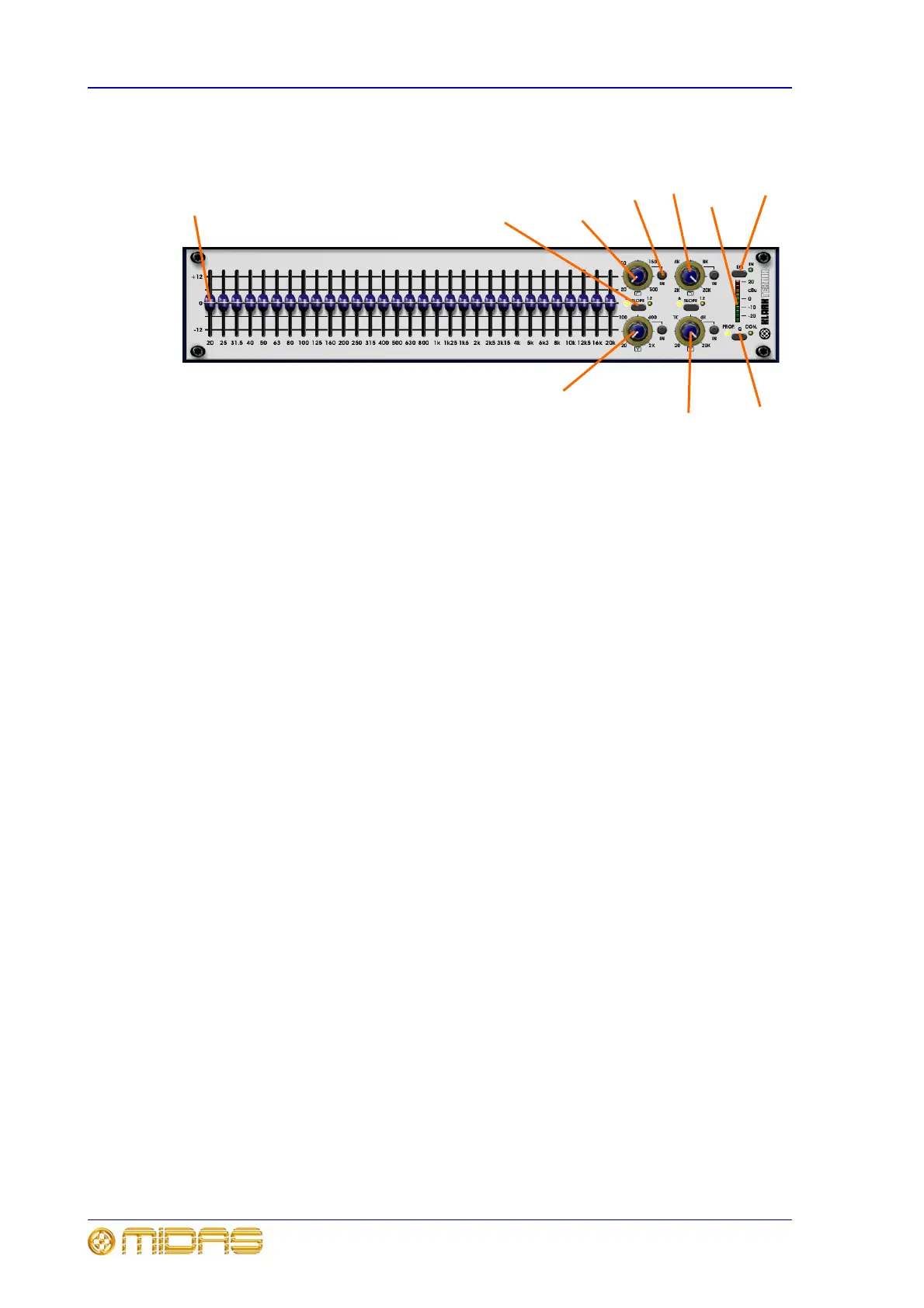
Front panel features
Graphic EQ section
Thirty one faders provide fine adjustment of each frequency band. The 31 frequency
bands are spaced 1/3 octave apart on the standard ISO 266 frequency centres. The
range of the equaliser bands may be switched between 6dB and 12dB via the SLOPE
button, with the active one being indicated by an adjacent illuminated IN LED. All the
functions of the GEQ can be bypassed via an EQ switch, such that the output will be the
same as the input.
Filters
The GEQ has one high pass filter, one low pass filter and two variable frequency notch
filters. Each filter is adjusted via a control knob on the GUI screen; see “Operating the
control knobs” on page 166.
To audition the effect of the filters, either the EQ in/out switch (which will also bypass
the GEQ) or the individual filter switch may be used.
1 Fader (31-off).
2 SLOPE button (2-off): for switching EQ
band of low pass filter between 6dB and 12dB.
3 Low pass filter: for adjusting the cut off
frequency, which is continuously variable from
20Hz to 500Hz.
4 High pass filter: for adjusting the cut off
frequency, which is continuously variable from
2kHz to 20kHz.
5 EQ button: for selecting EQ. The
adjacent green IN LED shows the EQ is on
(illuminated) or is being bypassed
(extinguished).
6 Level metering: 10-segment meter
shows the incoming signal level and is pre-EQ
(but post-gain control). Clipping is post-EQ
(and post-gain control), such that internal
clipping due to excessive EQ, that is, if a high
input level is further boosted by the use of EQ,
will also be shown. The LED functions are: two
red LEDs illuminate when signal has exceeded
+20dBu and is being clipped; two yellow LEDs
illuminate when signal level exceeds 0dB
(range is between 0dB to +20dB); and the top
five green LEDs encompass the signal level
range of between 0dB and -40dB, while the
bottom one illuminates when the signal has
exceeded -40dB.
7 Q PROP./CON. button: for selecting
proportional Q or constant Q modes.
8 Notch filter control knob: for adjusting
the position of the notch filter within the range
20Hz to 20kHz.
9 Notch filter control knob: for adjusting
the position of the notch filter within the range
20Hz to 2kHz.
10 IN LED (4-off): illuminates to show that
its associated filter is on.
1
2
3
45
8
9
6
7
4